Start Here:
ISO 7637: “Road vehicles — Electrical disturbances from conduction and coupling”
ISO 7637 is the automotive standard that sets out test methods for evaluating conducted immunity at the module level.
ISO 7637 defines test methods for determining how modules react to transient disturbances (conducted immunity).. ISO 7637-1 sets out general principles and can be purchased and downloaded from the ISO. It has four separate parts, with parts 2, 3, and 4 outlining specific test methods. A summary of what is in each part is included below.

For a given electronics module that draws typical 12V power, testing to both ISO 7637-2 and -3 will likely be needed. For units that interface with shielded high voltage power lines in an electric vehicle, ISO 7637-4 will apply. There are a lot of transients associated with operating a car/bus/truck–power surges on startup, transients from large inductive loads (motors) switching on and off, transient interruptions as connections are jostled loose by the bouncing of the car over roads for multiple years, etc. Testing for conducted immunity can be a significant portion of your overall EMC testing schedule.
ISO 7637 shares with ISO 11451 the structure of evaluating unit performance based on a functional performance status classification system, which is useful even outside the automotive industry.
ECE Reg 10: “Uniform provisions concerning the approval of vehicles with regard to electromagnetic compatibility”
ECE Reg 10.06 is a key automotive standard for manufacturers planning to sell vehicles in Europe.
UN/ECE Regulation No. 10 is a key automotive standard for manufacturers planning to sell vehicles in Europe. It is officially on its 6th revision (which can be freely downloaded here) and has been amended twice, most recently in 2022. Revision 7 is currently in work. It is an official publication of the United Nations Economic Commission for Europe. Ultimately a vehicle manufacturer will apply for “type certification” for a given vehicle line to be sold in Europe. In addition to the paperwork, a representative vehicle will need to be tested to ECE Reg 10 in the presence of an official EU witness.
It covers immunity, emissions, and the specific hazards concerning plugin electric vehicles with concern to the power grid. The limits for different tests are found in Appendices 2 - 7. The test method details are found in Annexes 4 - 22. In general, ECE Reg 10 adopts the following international standards:
CISPR 12 for off-board radiated emissions
ISO 11451-2 for off-board radiated immunity
CISPR 25 for radiated emissions from modules
ISO 11452-2, 3, 4 or 5 for radiation immunity of modules
ISO 7637-2 for module-level immunity to transient disturbances
The following apply to plug in electric vehicles in their charging mode only, either at the component or vehicle level:
IEC 61000-3-2 and -12 for measuring the harmonic conducted emissions on the AC power lines
IEC 61000-3-3 and -11 for measuring voltage flicker on AC power lines
CISPR 16-2-1 to measure RF conducted emissions
CISPR 22 to measure RF conducted emissions on wire network port
IEC 61000-4-4 for conducted immunity to fast transient/burst disturbances
IEC 61000-4-5 for conducted immunity to power surges
TIP:
Because ECE Reg 10 has detailed test setups for adapting various international EMC standards to its exact automotive concerns, you can learn a lot about EMC standards and testing by reading through this freely available document.
ISO 11451: “Road vehicles — Vehicle test methods for electrical disturbances from narrowband radiated electromagnetic energy”
ISO 11451 is a collection of test methods addressing vehicle level immunity to electric fields.
ISO 11451 is a collection of documents that describe automotive test methods for testing at the vehicle level to show immunity to various levels of electromagnetic environment. You can purchase 11451-1 here, and the same site has the other parts available as well. The parts are all revised on their own schedules, with Part 1 (current version published in 2015) expected to have a new revision published in 2024.
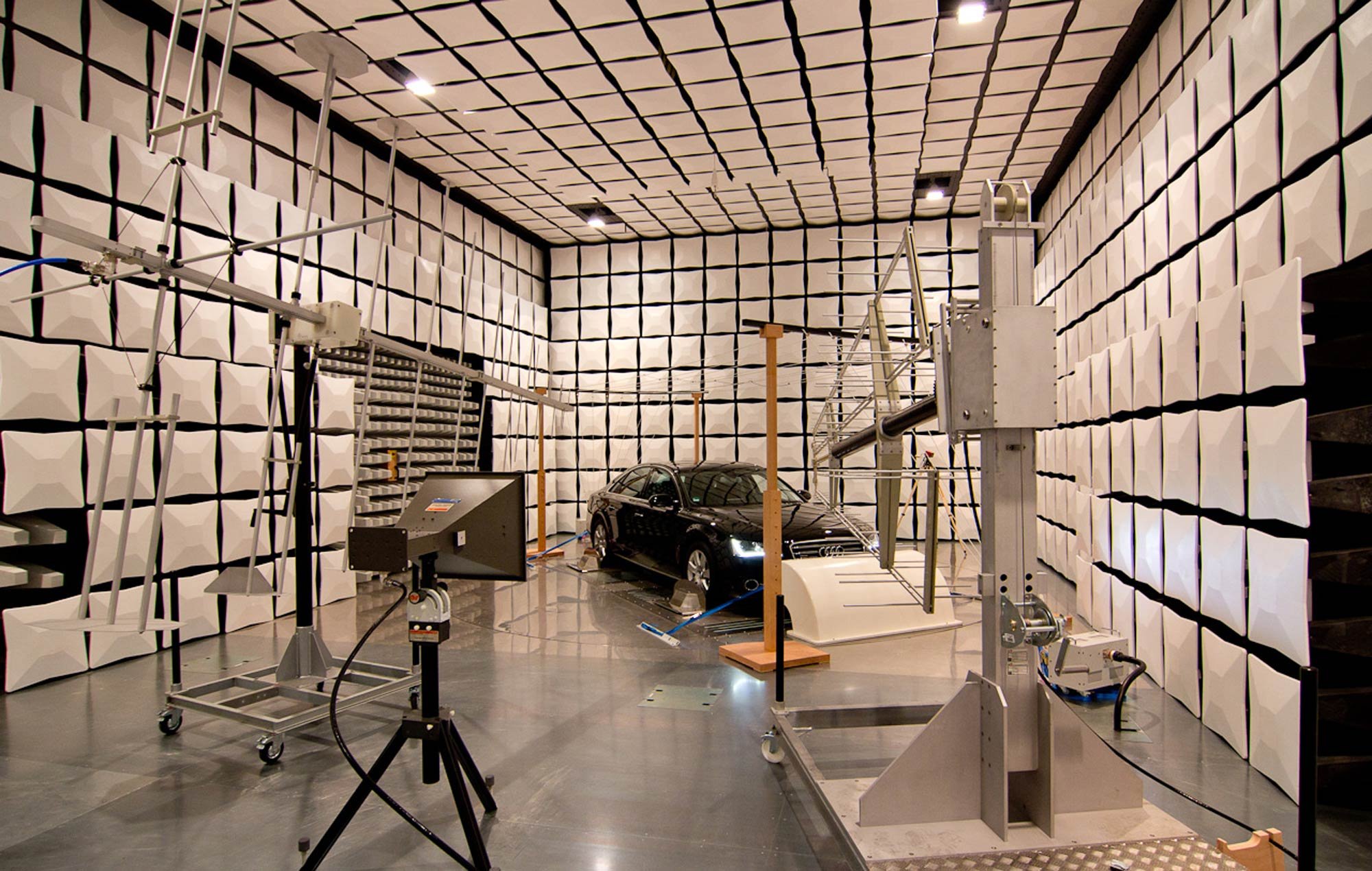
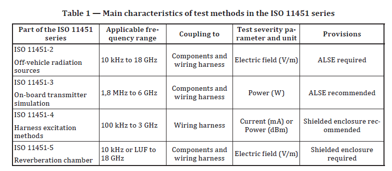
ISO 11451 is applicable to any kind of passenger car or commercial vehicle, whether traditional internal combustion engine or electric. Its test methods cover the frequency range 10 kHz - 18 GHz, but it is more often applied within a narrower range, such as 1 MHz - 2 GHz. Table 1 lists the different test methods available.
*LUF = lowest usable frequency of a particular reverb chamber.
TIP:
Remember that the plane wave illumination at each frequency in ISO 11451 testing isn’t a constant continuous wave. Different modulations are applied to different frequency ranges to better capture real world threats.
TIP:
ISO 11451 defines a set of functional performance status classifications (seen below). Widely used in the automotive industry, these categories can be helpful in defining the success criteria for immunity/susceptibility testing for many complex systems, either at the platform or module level. When a device under test has many functions, some of them may be more critical than others. For instance, if the infotainment system gets knocked offline, that’s inconvenient for the user, and the manufacturer may want to address the issue if it happens at too low of a field strength, such that it might happen often. On the other hand, if the headlights can get turned off by any of the test exposures, that would be a major safety concern that would have to be addressed. Combining the criticality of different functions with the performance status classifications from ISO 11451 in a test plan can be a good way to predetermine which “failures” or “anomalies” are acceptable and which must be labeled failures and fixed. It’s a more detailed framework than the “must function normally” criteria found within some immunity/susceptibility test plans.

CISPR 36: “Electric and hybrid electric road vehicles - Radio disturbance characteristics - Limits and methods of measurement for the protection of off-board receivers below 30 MHz”
CISPR 36 is specific to electric vehicles and covers low frequency magnetic fields, 150 kHz - 30 MHz.
CISPR 36 is a relatively new standard, with its first official release in 2020. You can purchase a copy here. While it is strongly influenced by an earlier Chinese standard, GB/T 18387, CISPR 36 has a narrower frequency range, starting at 150 kHz instead of 9 kHz. It stops at 30 MHz, which is where CISPR 12 picks up.
CISPR 36 is unusual in focusing on low frequency magnetic fields, although its purpose is still to protect the radio reception of receivers outside the vehicle. On board receivers are protected by CISPR 25, same as any other vehicle. CISPR 36 only applies to ground vehicles with electric motors that draw power from a traction battery with voltage between 100 and 1000 V.
CISPR 36 uses magnetic field (loop) antennas positioned 3 m away from the vehicle. Measurements are taken with the vehicle at speed (on a dynamometer) at four positions (in front, behind, and to either side of the vehicle) and two orientations, for a total of eight sweeps. The sweeps are from 150 kHz - 30 MHz with a resolution bandwidth of 9 kHz. The limits are the magnetic field strength in dBuA/m, taken as a quasi peak (QP) measurement. In general most test operators will sweep in peak detection mode first, and only return to take QP measurements at specific frequencies where the peak value is above the QP limit. (See our explainer on quasi peak measurements.) Measurements can be taken in a semianechoic chamber or properly characterized open air test site, not in a reverb chamber.
Right now CISPR 36 does not address the charging mode, either via plug in or wireless power transfer (WPT). Other committees are looking into those modes, and ANSI C63.30 was published in 2021 describing test methods for WPT specifically.
CISPR 25: “Vehicles, boats and internal combustion engines - Radio disturbance characteristics - Limits and methods of measurement for the protection of on-board receivers”
CISPR 25 is an automotive standard that covers the main emissions testing methods needed to ensure self-compatibility between a vehicle and its own on-board receivers..
CISPR 25 governs emissions related to automotive components, both for ground vehicles and boats. It includes both component level and vehicle level tests. The current version is the 5th edition published in 2021, and you can purchase it here. Some of the component level test methods in CISPR 25 are very similar to comparable methods in MIL-STD-461, but they are not at all similar to emissions testing done for the FCC via ANSI C63.4. (You can check out one of my presentations that dives pretty deep into that comparison.) And obviously MIL-STD-461 does not have an equivalent of the full vehicle testing found in CISPR 25.
More than anything, CISPR 25 is aimed at self compatibility. Historically this meant limiting emissions that would interfere with onboard radios (AM/FM/DAB) so as to avoid customer complaints. Today with vastly more complex vehicle electronics and the HV components of EVs, there are a lot more “victims” that can be affected by emissions than just AM/FM radio. [Aside: I once worked on troubleshooting an EV where a CISPR 25-noncompliant inverter interfered with the vehicle’s twisted/shielded CAN lines to the extent that whenever the driver stepped on the “gas” pedal, the battery control module shut down, requiring a full restart. In that case the solution was improving the shield terminations on the CAN lines.]
In general, vehicle level tests are done in four possible modes: key on, engine off; internal combustion engine (ICE) in driving mode (spinning wheels on a dyno); EV in charging mode, and EV in driving mode. (A plugin hybrid electric vehicle would need to test in all four modes.) For testing on the full vehicle, you need to disconnect each antenna from its receiving radio module, and feed the antenna coax into the measurement receiver, often through an impedance matching unit.
At the component level, CISPR 25 includes both conducted and radiated emissions tests. Conducted emissions can be measured via voltage measured from an artificial network (AN, equivalent to a LISN in the aerospace/defense world), or via a current probe measured at a minimum of two locations along the cabling. For radiated emissions the main test method is conducted in a semi-anechoic chamber, with an informative Annex F describing a stripline method. It currently does not provide for a reverb chamber method.
TIP:
Pay close attention to the flowchart in Figure 1 of CISPR 25. Because of the different limit lines for different detectors(peak, quasi peak, and average) and how they apply to narrowband vs. broadband noise sources, there are a lot more steps before saying something definitively “passes” or “fails” than in a method like MIL-STD-461 RE102.
TIP:
CISPR 25 is a critical standard for the HV components of electric vehicles as well as the traditional 12 Vdc systems. Take this as one consultant’s experience, but every EV on which I’ve done troubleshooting had problems with an HV component that failed CISPR 25 testing (particularly inverters and DC/DC converters). I have not yet had to troubleshoot on an EV where every component passed CISPR 25. It is a major challenge to design an HV inverter that passes CISPR 25 limits, but it can be done–and it’s likely worth investing the extra time to design a compliant system, or the extra money to buy one. You can also see my presentation on Noise Sources in EVs for more.
TIP:
Getting to the audio head unit (radio) to disconnect the AM/FM radio for vehicle level testing can be painful, and the sweeps can take a long time, especially if there are a lot of frequencies where quasi peak measurements are needed. CISPR 25 is not a regulatory test, so judgment of compliance is up to the manufacturer. It may make more sense to run the vehicle and tune through stations looking for audible problem areas, then only run the CISPR 25 sweeps on frequency ranges where there are issues. Making sure the audible test is legitimate has its own set of challenges, but once set up, it can run considerably faster than full CISPR 25 sweeps.
IEEE 1560: “IEEE Standard for Methods of Measurement of Radio-Frequency Power-Line Interference Filter in the Range of 100 Hz to 10 GHz”
IEEE 1560 contains test methods for testing power line filters.
IEEE 1560 was first published in 2005, then reaffirmed in 2012. It has been inactive since 2023. It’s available for purchase here. Inactive doesn’t mean that there’s anything wrong with it, it mostly means that people got behind on the paperwork. We were able to approve a renewal effort to move forward at the EMC Symposium in the summer of 2024, and it will be up for IEEE SA approval in the Fall. Once that comes through, a working group will be organized under the leadership of Dasha Nemashkalo of the University of Twente. If you would like to be involved in that effort, please contact me at standards@emcunited.com.
Once upon a time, a customer asked for help evaluating the effectiveness of certain power line filters they had procured. They were building a secure shield room and wanted in situ measurements to determine if the filters were performing as advertised. I looked up the filters and the marketing copy said: “Our shielded room filters are designed to meet or exceed the requirements of MIL-STD-220 with 100 dB attenuation from 14 KHz to 10 GHz.”
So I looked up MIL-STD-220 (download here) and found a test method that looks like this:

Which assumes 50 Ohm coaxial connections throughout. This makes perfect sense for the kind of RF filters that MIL-STD-220 was written for (“Method of Insertion Loss Measurement”, freely available here). It does not make sense for systems that look like this, with not a coax connector in sight:

It turns out that prior to the first publication of IEEE 1560 in 2005, there was no widely accepted standard document governing the testing of power line filters, so the industry picked up the closest related standard, MIL-STD-220 for RF filters. Now, I have to admit, the proof is in the pudding: manufacturers have been testing to this method for decades and obviously haven’t had any massive customer revolts over inadequate performance. So something is working right-most probably some excellent design practices by the suppliers in question. But in any sane universe, we would have switched to the more tailored and rigorous IEEE 1560 document by now. (I went on a bit of a rant about this during a talk I gave to the SE Michigan EMC chapter on how different standards stack up to each other.)
The following test methods are included in IEEE 1560:
Quality assurance--No load (10 kHz to 1 GHz)
Quality assurance--Loaded (10 kHz to 20 MHz)
RF characteristic mismatched impedance--No load (100 kHz to 30 MHz)
Variable source impedance attenuation measurement (100 Hz to 100 kHz)
Attenuation measurement (100 kHz to 30 MHz)
Aperture leak test by electric fields (1 GHz to 10 GHz)
Voltage drop and waveform quality test (linear/non-linear loading)
S-parameter measurement (100 Hz to 30 MHz)
Eagle-eyed readers will notice that the only test covering 30 MHz - 1 GHz is “Quality assurance--no load”, which is described as a workmanship test more than a performance characterization measurement. As we move forward with the 1560 renewal effort, this is the kind of thing we’ll need to decide how to address.
GSFC-STD-7000B: “General Environmental Verification Standard (GEVS) for GSFC Flight Programs and Projects”
GSFC-STD-7000B contains something like a version of MIL-STD-461 specifically tailored for small, metal chassis, science satellites
GSFC-STD-7000, affectionately known as GEVS, is a huge document covering a wide variety of environmental testing, including shock, vibe, thermal, etc. For our purposes we’re only concerned with Section 2.5 on EMC. Written by John McCloskey and Ken Javor, it is worth making sure to get Rev B. While both revisions have the same approach--tailoring MIL-STD-461 for the kind of missions most common at Goddard Space Flight Center--Rev B has a greatly expanded Section 2.5.3, which serves the same function as the appendices of MIL-STD-461. It is a wealth of additional information and context on each test method and how it came to be specifically tailored in this document. This is hands-down one of my favorite standards documents, and I refer to it even when I’m not working on Goddard or NASA programs. The document is freely and officially available here.
The tailoring in GEVS is based on certain assumptions that hold true for the most common GSFC programs:
Uncrewed satellites
Generally cubes, generally smaller than 2 meters on a side
They have metal chassis
They never use structure for current return
28 Vdc power bus, sourced from batteries and recharged from solar panels
The table below shows a summary of the requirements they arrived at, and a top-level comparison with MIL-STD-461.

TIP:
One thing that I appreciate is that it includes a test not found in MIL-STD-461, which is a common mode conducted emissions test. It’s found in Section 2.5.2.1.2. While MIL-STD-461 CE101 and CE102 have differential measurements taken from a LISN, this test uses a current probe to measure the common mode currents flowing on the cables--which is one of the prime indications of potential crosstalk or radiated emissions problems. It also has a method for extending the test range from 30 MHz up to 200 MHz using an absorbing clamp as described in CISPR 16-1-4. GEVS section 2.5.3.3.2.1 contains an extremely thorough and well-thought-out discussion of why absorbing clamps are appropriate at the higher frequencies, and it left me thoroughly convinced. For people in the automotive industry, the 30 - 200 MHz is particularly critical for EVs seeking to pass CISPR 12 testing, and the common mode, absorber clamp method may be a useful pre-compliance test for that purpose.
TIP:
Instead of the more commonly found 50 uH or 5 uH LISNs used in much MIL-STD-461 and automotive component testing, GEVS uses a 10,000 uF cap network. It’s worth reading the rationale in Section 2.5.3.2.2 (with related discussion in MIL-STD-461 Rev G Section A.4.3.6) to broaden your thinking about LISN/Artificial Network choice. For more on LISNs, see this post.
ISO 11452: “Road vehicles — Component test methods for electrical disturbances from narrowband radiated electromagnetic energy”
ISO 11452 is a standard with multiple parts and test methods that covers testing components that will go on vehicles (cars, trucks, etc.) for immunity.
ISO 11452 covers automotive components for immunity testing--with, as we see with several other standards, a whole lot of parts that can be bought separately. You can see which parts cover which test methods in the tables below. You can start by looking at ISO 11452-1 (“General principles and terminology”) which is available for purchase here. The current version is from 2015 and a new revision is expected in the next year or so.


ISO 11452 uses CISPR 16 to govern the measurements equipment used. Annex A of ISO 11452-1 has a very useful normative guide on how to classify the performance of different functions during testing (you would not call a test a failure if an infotainment system spontaneously reset during moderate level testing; the brake system doing the same thing would be considered a critical failure).
You might notice similarities between ISO 11452 and its various parts and those of SAE J1113. That’s not a coincidence--J1113 was essentially the North American version of the same document until they came into agreement.
TIP:
If you have the facility available, testing in a reverb chamber (ISO 11452-11) is often the fastest way to test and also the one most likely to find problems. That sounds like a bad thing, but it’s much better to find problems when it’s one component in a chamber instead of troubleshooting an entire vehicle.
IEC 61000: “Electromagnetic Compatibility--”
IEC 61000 is a major umbrella standard that encompasses a wide range of documents within it, covering limits and test methods for a variety of scenarios.
The IEC (International Electrotechnical Commission) produces, roughly speaking, a gajillionity different standards. Within that extensive list, IEC 61000 is the one that tackles all of EMC. Within IEC 61000, there are only maybe a few jillion subsections. The IEC website has all the sections available for purchase; you can start with 61000-1-1 here. It is good that you can purchase only the sections you need; however the tradeoff is that if you’re a lab that deals in a wide range of test methods you may need to make a significant investment to purchase all the different official copies you’ll need.
I should note that within the IEC, Technical Committee 77 (TC77) has the primary responsibility for IEC 61000. CISPR is another set of committees within the IEC umbrella.
The basic structure of the numbering is IEC 61000 dash part # dash section #. The parts are broken down thusly:
Part 1: General
Basic concepts (fundamental principles, definitions, terminology) - interference model
Functional safety (what a safety function does and measures of it being performed satisfactorily)
Measurement uncertainty
Part 2: Environment
Description of the environment
Classification of the environment
Compatibility levels
Part 3: Limits
Emission limits
Immunity limits (insofar as they do not fall under the responsibility of product committees)
Part 4: Testing and measurement techniques
Measurement techniques
Testing techniques
Part 5: Installation and mitigation guidelines
Installation guidelines
Mitigation methods and devices
Part 6: Generic standards
Generic emission and immunity requirements in various environments
[Parts 7 and 8 are not currently used]
Part 9: Miscellaneous
This may be overstating the case, but most EMC engineers will probably spend more time with the sections of Part 4 than any others. For instance, IEC 61000-4-2 has the standard test method on ESD. It’s used by the automotive industry and has recently been adopted into the MIL-STD arena by way of MIL-STD-461 Rev G, CS118.
As with MIL-STD-461, there are so many important sub-sections of IEC 61000 that I plan on tackling them in individual articles. I may never get to them all, but over time I’ll do my best.
TIP:
MIL-STD-461 with CS118 is freely available here, and has almost identical content to 61000-4-2. They’re also both the same as ISO 10605.
CISPR 32: “Electromagnetic compatibility of multimedia equipment - Emission requirements”
CISPR 32 is the international standard most comparable to the FCC standard on consumer electronics.
CISPR 32 governs emission, both conducted and radiated, from “multimedia equipment”, which encompasses most consumer electronics, such as computers, televisions, radios, etc. It is the international standard most similar to the testing of unintentional emitters required by the FCC and found in ANSI C63.4. CISPR 35 is the corresponding immunity requirement document. In the EU, CISPR 32 is incorporated as a regulatory document with the number EN 55032.
The most current version is from 2015 with amendments in 2019 and can be purchased here. It superseded CISPR 13 and 22, which makes sense--CISPR 13 had covered broadcast media equipment and CISPR 22 had covered IT/computer equipment, and they were managed by different committees. That was fine until digital TV, digital broadcasting, and then streaming became ubiquitous--now broadcast equipment was IT equipment and it all got very confusing (no one likes testing their equipment twice). CISPR 32 is the result of a harmonization effort. It uses CISPR 16 to govern the standards of its measurement equipment. Officially the standard covers the frequency range 9 kHz - 400 GHz, although most equipment does not need to be tested to the extremes of that range. Generally equipment will be tested up to 6 GHz, but check the tables carefully--the upper testing limit depends on the frequency usage of the equipment under test. The conducted emissions testing will generally start at 150 kHz.
Like the FCC, CISPR 32 classifies units as “Class B” if they are intended for use in residential environments; those have stricter emissions requirements. Everything else is “Class A”. There are limit lines for both quasi-peak (QP) and average detector methods; see this explainer for information on quasi-peak and how to minimize QP test time. Also like FCC, limits are provided for measurements at both 3 m and 10m distances.
Interference Technology has good articles on the 2012 version of CISPR 32 by Dan Hoolihan and the 2015 version by Ghery Pettit.
TIP:
The actual limits that are required to be met are found in Annex A of the document.
FCC 47 CFR Part 15
This is the part of FCC regulations that covers normal electronics, as opposed to systems that have intentional RF transmitters and receivers.
Title 47 of the Code of Federal Regulations, Chapter I, Subchapter A, Part 15, “Radio Frequency Devices” is one of the main ways the Federal Communications Commission controls electronic devices from interfering with other systems in the same area. Part 15 is publicly available. It deals with items that are capable of generating RF interference and aren’t operated by licensed users (an example of licensed operators would be Ham radio enthusiasts).
Part 15 defines Class A and Class B digital devices. Class A devices are specifically for use in industrial environments, such as a controller unit for an industrial furnace. Class B devices are meant for residential use (even if they’re often used in business environments, such as a laptop). The limits on emissions are more strict for Class B devices, since they are used in open environments, whereas the Class A units are assumed to be used in environments where stricter controls on unit-to-unit interference are possible. Subpart B has the quasi-peak and average limits for unintentional radiators, units that do not have an intentional RF transmitter capability. (For more on quasi-peak measurement, here’s an explainer.)
For consumer electronics, the main route of compliance is the Supplier’s Declaration of Conformity. The idea is that the equipment manufacturer has a product sample tested to ANSI C63.4 for both conducted and radiated emissions, and keeps a copy of the test report that shows passing results. (Products that have intentional radiators, such as a Bluetooth or WiFi element, need to test to ANSI C63.10.) If there is ever a question about the product causing unwanted interference problems, the FCC will contact the supplier for the evidence of compliance. Every year several companies are fined for operating non-compliant equipment that ends up jamming neighboring systems, and the fines can add up quite quickly.
There is no immunity requirement from the FCC--their priority is to make sure equipment available on the market does not cause RF interference to other systems. They don’t particularly care whether your product works or not, which is what immunity standards fundamentally address.
TIP:
FCC testing is most similar to CISPR 32. Testing to CISPR 25 or MIL-STD-461 (RE102 or CE102) is not directly comparable to FCC limits, since the test setups are too different.
Quasi-Peak Explainer
Peak and Average measurements are pretty self-explanatory, but what on Earth is Quasi Peak (QP)?
If you think about old-school over-the-air radio (AM/FM), you’ve almost certainly heard static on a weak channel. If you think about the noise that could be coming through your car stereo speakers, which is more annoying, background/hissing static, or a continuous shrill tone?
The idea that a continuous screech is more annoying than background pops and clicks is the rationale behind QP measurements. In this method, you dwell at each frequency step long enough to apply weighting to the signals you find there. If you have a continuous wave (CW) signal, that will come through as a single tone. However if you have transient noise that is bouncing around and only present during part of the dwell time, that would be the popping and hissing type of noise. QP measurements weight CW signals more heavily. Thus for FCC or CISPR 25 testing, you have to show measurements compared to the QP limit line, in order to be less annoying to the public.
In a world where all our noise sources are stable, which is what we’re ideally trying to achieve in testing, then there can’t be any signal “worse” than a CW signal when measuring for QP. However, a peak detector will easily capture the peak of a CW signal, no problem. And a peak sweep is much faster than QP, since you don’t have to dwell at each frequency so long. So what is typically recommended is to do a peak sweep that covers the full frequency range first. If you pass that, it’s accepted that you will obviously pass the QP measurements as well. If there is a peak value over the limit, then you can return to that specific frequency range and do a longer-dwell QP sweep only in that area, saving test time.
TIP:
I’d like to note that the rule that QP is always less-than-or-equal-to Peak only holds when testing conditions are static. If you are testing a more complex system that may have functions turning on and off during testing, it is possible to see QP values higher than Peak at the same frequency. That’s because the measurements are taken at different times, and the vehicle or other DUT may have turned on something in a later test that wasn’t there originally (e.g. a continuously running electric vehicle (EV) turns on its cooling system for thermal management partway through a test). That’s not to say that you should always run a full scan on QP detection; that would take forever. But if you see QP greater-than Peak, that can be an explanation.
LISN Explainer
LISNs are used in multiple different test methods, with different names and characteristics. What the heck are they, anyway?
I’m indebted to Ken Javor’s 2023 article “Line Impedance Stabilization is in its Seventieth Year and Still Going Strong”.
When we test equipment/boxes/modules for EMC, we are testing them in very different conditions than their installations. For instance, usually there’s only one module being powered by only one power supply. In a real installation, there would be power distribution points that feed many different modules (e.g., in a car, your average 12V module gets power from the body control module (BCM) instead of directly from the alternator or 12V battery, and the BCM may be sending power to dozens of modules). There’s a lot that will vary from installation to installation, depending on the platform, end use, construction, etc.
Enter the Line Impedance Stabilization Network (LISN), also sometimes known as an Artificial Network (AN). The clearest picture I’ve yet found to represent its purpose is the one below from GSFC-STD-7000B. The LISN is meant to represent Zs from the picture below.

If you assume that power is distributed via a single wire running 5 cm above structure, and structure is used for current return, then you can reasonably estimate 1 uH/m inductance from all that wiring. On a very large platform like a naval vessel, 50 m of wiring isn’t unheard of--and now you know the origin of the 50 uH LISN. The very first LISN design, from 1953, is the 5 uH LISN (aircraft in particular were smaller back then), and the 5 uH LISN is still used when appropriate today.
There are plenty of variations. For instance, the typical Goddard Space Flight Center project (JWST notwithstanding) is a small science satellite, a cube not much more than 2 m on a side, with a 28 Vdc battery recharged by solar arrays and never using structure for current return. That’s a very low inductance arrangement, and thus they use a stabilization network with a pair of 10 uF feedthrough caps and a 10,000 uF line-to-line cap.
LISNs also help in providing repeatability of measurements across tests and across different labs. Thus if you’re doing FCC testing, you’ll be using the LISN specified in ANSI C63.4 no matter what your final installation is.
TIP:
Take a moment to consider what flavor of LISN is most appropriate for the end installation your product will be used in. MIL-STD-461 Rev G Section A4.3.6 has tailoring guidance on this topic.
ANSI C63.4: “American National Standard for Methods of Measurement of Radio-Noise Emissions from Low-Voltage Electrical and Electronic Equipment in the Range of 9 kHz to 40 GHz”
ANSI C63.4 contains the main test methods used to verify compliance to FCC Part 15 unintentional emissions limits, making it key for consumer electronics.
ANSI is the American National Standards Institute, and C63 is its committee specializing in EMC matters, particularly test and measurement. There is close coordination between ANSI C63 and the IEEE EMC Society and IEEE Standards Association. C63.4 relates to measuring EM emissions from normal electrical and electronic equipment, and it can be purchased here. Most importantly, it is the standard referenced by the FCC (47CFR15) and Canada (ICES-003) for consumer electronics compliance to FCC Part 15 emissions limits. The current version is from 2014, and it is currently being revised for the next release. Which is a great time for us to remind you that it is free to participate in ANSI C63 standard working groups, so please get in touch with us if this is something you’d like to be involved with--we can put you in contact with the right people to inquire.
C63.4 is one of the broad standards, something that works towards being comprehensive instead of very narrow. For one thing, it deals with both conducted as well as radiated emissions. It covers the test equipment needed for this testing, which includes equipment for different test methods covering the same frequency range. It has a section on measuring IT equipment specifically before moving onto more generic methods. It also has a number of normative and informative Annexes providing more information, context, references, etc. The intent is always to protect nearby equipment, be that a Ham radio, a computer or a pacemaker, from interference.
The standard covers test instrumentation (including some very useful information about test antennas, the uses & limitations of different types), test site requirements, considerations for test setups, discussion of relaxations for sporadic transient emissions, and the following specific test methods:
AC power line conducted emissions, 150 kHz - 30 MHz
Radiated emissions, 9 kHz - 40 GHz (for FCC testing, only 30 MHz - 1 GHz is applicable)
Radio noise power using an absorbing clamp
Test setups specific to IT equipment
Recommendations for testing unintentional emitters other than IT equipment
Radiated emissions testing using TEM waveguides, 30 MHz - 1 GHz
TIP:
It should be noted that the testing done in ANSI C63.4 is significantly different than that found in the aerospace/defense/automotive sections. So a unit that qualifies to FCC limits can’t be automatically said to meet MIL-STD-461 RE102 or CE102, CISPR 25, or RTCA DO160 Section 21--or vice versa. For an explanation of the details, see this presentation Ms. Burnham gave to the SE Michigan chapter of the IEEE EMC Society early in 2024.
A Resource for Information on EMC Standards
Introduction to the resources you can find here on EMC standards, plus my philosophy on standards & standards development.
The world of EMC standards can be intimidating, to say the least. I learned about standards within days of learning of the existence of EMC--working at NASA meant becoming deeply familiar with MIL-STD-461, among several others. But I really became a “standards geek” when I jumped from aerospace to automotive and saw how we’re all taking the same physics & electrical engineering and writing similiar-yet-importantly-different standards based on the varying realms of application. Since then, my time as Vice President of Standards for the IEEE EMC Society has given me a deeper appreciation for the universe of standards and the processes and people that create them.
On this site, I hope you’ll find answers to questions like: what standards apply to my product? Where can I find them? What are similar standards that I could look at to learn more? What are some of the tips, tricks, and pitfalls associated with certain standards?
I also hope you’ll consider getting involved in standards development. Standards are written by working professionals, and more than most disciplines, EMC lives and dies by standards. It seems like without them, it’s hard to get people (::cough:: managers ::cough::) to take EMC issues seriously. You don’t need to wait until you’re looking back at a 45 year career to get involved--we need people at all career levels, especially people who are seeing how things are playing out on the ground right now. If you see a standard that needs improvement (most standards are revised/renewed every 5-10 years) or an area where no standardization exists but it really should, then please get in touch. I can likely put you in contact with the right people or organizations to see if we can make it happen.
This site is not yet a fully comprehensive list of EMC standards (if such a thing is even possible). I’ll be adding to it regularly as the site grows and as I learn about new developments. If you see anything that should be added or corrected, please email me, standards@emcunited.com. I’ll happily make updates (after double-checking info, of course) and credit whoever brings new information to my attention.
In the meantime, here’s a quick cheat sheet for standards that are key if you’re in certain industries:
Consumer electronics: American
Consumer electronics: European
Automotive: Component level
Automotive: Vehicle level
CISPR 36 (EVs only)
Defense
Aerospace
Medical
Test instrumentation/measurements
TIP:
Always read the appendices! Almost every standard has informative (for context and extra details) and/or normative (additional parts of the standard) appendices or annexes that shed invaluable additional light on the subject matter and the reasoning behind the standard’s choices. If you look at the experience of the cumulative membership of these standards working group committees (the ones that draft the documents), the appendices often contain the knowledge and lessons learned from over a hundred of years of lived experience.
For all the standards articles and information you find on this site, please double-check information before acting on it (a good idea for so many areas of life). My information is only as good as my most recent source, and some of the standards I have been reading may have since gone out of date or been revised. Commentary is based on my own experience and opinions (and if I’ve learned one thing about EMC engineers, it’s that between 3 engineers you’ll probably get at least 5 opinions on a given topic).
Index to other articles on the site:
MIL-STD-461: “Requirements for the Control of Electromagnetic Interference Characteristics of Subsystems and Equipment”
MIL-STD-461 is one of the core EMC standards, having evolved with military applications since WWII. It is widely used in the aerospace and defense sectors.
MIL-STD-461 is a landmark document in the world of EMC standards, and there are a lot of other standards that derive from this one. The easiest place to find a copy of MIL-STD-461 (free, as most government standards are) is here, or the official site is here. The current edition is Rev G, and the working group for the standard is currently drafting Rev H.
MIL-STD-461 is more of a document that specifies test methods than a strict requirements document, and while it has suggested limits for many of the tests, in most cases those limits should be tailored. For general aerospace and defense projects MIL-STD-464 is the actual requirements document, and the tests in MIL-STD-461 are how you document compliance to the EMC requirements.
TIP:
Tailor, tailor, tailor! Beware of any project that simply tells you to “meet 461”--even accepting 461 as the overarching requirement, tailoring 461 is key for saving testing time and budget and not wasting resources designing to inappropriate or inapplicable requirements. I’ll discuss this more in articles dedicated to each test method.
TIP:
Read the appendices! More than most standards, the committee behind MIL-STD-461 documents background information for every section of the main document. This includes context, lessons learned, and why different changes have been made over time. There’s a wealth of information in there.
TIP:
MIL-STD-461 does not have a requirement to perform testing in a certified lab. While many of the labs that have the equipment needed to perform 461 testing are certified (to ISO, by ANLAB or A2LA, etc), that is not required. Testing in an uncertified lab or your own facility is allowed as long as you can meet the test equipment and test reporting requirements.
CISPR 12: “Vehicles, boats and internal combustion engines – Radio disturbance characteristics – Limits and methods of measurement for the protection of off-board receivers”
CISPR 12 is a key automotive standard that details the test method for ensuring cars and other vehicles don’t emit too much RF energy at a distance, usually 10 m away. It’s often referred to as an “off-board radiated emissions test”.
CISPR 12 is one of the critical standards that apply to full vehicles, whether using traditional internal combustion engines, electric vehicles, or hybrids. The current edition is from 2007, with amendments in 2009, and you can find it for purchase here. The intent of the requirement is to protect radio receivers that are external to the vehicle, such as an FM radio in a nearby house, or the two-way communication system of a passing ambulance. It applies to boats and ground vehicles, with both internal combustion or high voltage EV engines. The test is generally at 10 m distance, although if only a 3 m separation between the vehicle under test and the test antenna can be achieved, the limits can be increased by 10 dB to account for the difference (this linear extrapolation is doable since both 3 m and 10 m measurements are reliably in the far field in the 30 MHz - 1 GHz range--don’t try this with 1 m measurements such as in CISPR 25).
TIP:
CISPR 12 has limits that are expressed in Average and Quasi Peak. Quasi Peak (QP) testing takes forever, so the standard recommends speeding things up by doing a Peak sweep first. If all the Peak values are below the QP limit lines, then it’s accepted that any QP measurements will also pass the requirement. (This is true probably 95% of the time, but not always.) In that case you’re done and you’ve saved yourself a lot of time compared to taking QP measurements. If there are specific frequencies where Peak values are over the QP limits, you can go back and take QP measurements at only those frequencies. Quasi Peak detection is a little strange and can be hard to track down information on, so see this Quasi Peak article for a quick explainer.
TIP:
Another way to speed up testing is to increase the bandwidth of your initial scan, keeping dwell time the same. If you pass the specified limit with the wider bandwidth, you can be assured that you would have passed with the smaller bandwidth. Then if you run into exceedances at a specific frequency range, you can go back and test that range with the smaller spec bandwidths.