Start Here:
IEEE 1302: “Guide for the Electromagnetic Characterization of Conductive Gaskets in the Frequency Range of DC to 40 GHz”
IEEE 1302 standardizes multiple test methods for characterizing conductive gasketing, and offers guidance on which test method to select for different applications.
Gasketing can be critical to achieving EMC success. Imagining a metal enclosure with a removable lid, that lid may not seat perfectly around the entire perimeter. There are plenty of reasons for this: number of fasteners, bowing of the material, gaps for other purposes, etc. EMI gaskets are conductive materials meant to seat in that perimeter and make contact with both the lid and the enclosure body, filling in potential gaps. There are about a million different kinds of gaskets, from conductive elastomers to beryllium copper fingerstock. Likewise, there are a lot of different ways to characterize how effective they are. No single method is perfect, so IEEE 1302 exists to provide descriptions of accepted standard test methods and guidance on which test to choose for a given application. IEEE 1302 can be purchased here.
Here are the main test methods discussed in IEEE 1302:
Transfer impedance based on SAE ARP 1705 (2006, Rev A)
Transfer impedance based on SAE ARP 1705 (2017, Rev C)
Relative aperture transmission based on MIL-STD-285 and/or IEEE 299, including SAE ARP 1173, MIL-DTL-83528G, and DefStan 59-103
Stripline method, per SAE ARP 6248 (2016)
Effective transmission aperture using total radiated power through a gasketed aperture
Slot aperture, modifying MIL-DTL-83528G to use a 3 mm x 500 mm slot instead of a 610 mm x 610 mm square to mount the gasketing material
Nested reverb chambers
Far-field TEM-t fixture, analogous to ASTM D4935-1989
Near-field H-t fixture, similar to TEM-t but measuring magnetic shielding performance
DC resistance measurement as a very basic check
In Table A.1 the document evaluates each test method on the following parameters:
Measurement principle/field condition
Parameter measured
Unit of measure
Size of measuring fixture
Test sample configuration
Sample size (minimum length needed)
Visual control on mechanical behaviour
Real mechanical construction details
Environmental and corrosion tests (salt fog/humidity)
Frequency range
Dynamic range
Repeatability
Measurement uncertainty
Remarks on SE value
The following paper by the chair and vice-chair also has detailed information of what went into the 2019 revision of the standard (which was originally published in 2008): J. Catrysse and D. Pissoort, "IEEE Std. P1302–2019: A Guidance Document for the Characterization of Shielding Gaskets," in IEEE Letters on Electromagnetic Compatibility Practice and Applications, vol. 2, no. 3, pp. 67-71, Sept. 2020, doi: 10.1109/LEMCPA.2020.3017349.
IEEE 1848: “Techniques and Measures to Manage Functional Safety and Other Risks with Regards to Electromagnetic Disturbances”
IEEE 1848 is a relatively new standard, focused on functional safety and electromagnetic resilience.
IEEE 1848 is an entry into the world of managing functional safety. It is currently unique in focusing squarely on EMC as part of the overall discipline. It can complement other functional safety documents such as ISO 26262 (automotive), ISO 14971 (medical), or IEC 61508 and IEC 61000-1-2 (electronics more generally). It was developed in concert with the IET “Code of Practice for Electromagnetic Resilience”, so that readers of either document will be speaking the same language. IEEE 1848 is available to purchase from the IEEE Standards Association website. It was published in 2020, and the first ever effort to renew and revise will begin in the next year or two. Please get in touch (standards@emcunited.com) if you’re interested in being part of that work.
IEEE 1848 focuses on the concept of EMR, electromagnetic resilience. It defines resilience as “The capacity to recover quickly or easily from difficulties, misfortune, or change; toughness.” The idea is that we can’t prevent every form of electromagnetic interference (especially as the electromagnetic environment continues to become more complex and higher frequency by the day). We also can’t test for every potential interference interaction, so we need to design systems that are resilient to those kinds of disturbances. There are sadly many examples of times when various electromagnetic interactions caused the loss of life, from the USS Forrestal disaster to medical devices malfunctioning.
Section/Clause 5 of IEEE 1848 has a straight-up checklist to go through in order to demonstrate EMR and functional safety. Then Annex A has all the details on how to apply each step of the checklist, including examples and references. The main categories of techniques and measures from the checklist are:
Project management, planning, and specification
System design
Operational design
Implementation, integration, installation, and commissioning
Verification and validation (including testing)
Maintenance, refurbishment, repair, overhaul, modification, upgrade, etc., over the lifecycle
Decommissioning
Integrating third-party items into the safety function
Even if you don’t have a requirement to follow IEEE 1848 strictly, going through the checklist can prompt you to think through aspects of your design that might be easily overlooked.
EMR is increasingly important with our increasingly complex and interconnected world of electronic systems. I encourage everyone to take a look at IEEE 1848 and consider adopting and adapting its approach to your systems.
IEC 60601-1-2: “Medical Electrical Equipment–General requirements for basic safety and essential performance–Electromagnetic disturbances–Requirements and tests”
IEC 60601-1-2 is a key standard that defines EMC requirements for medical devices.
IEC 60601-1-2 is a key standard for those seeking to certify electrically powered medical devices, whether for a hospital, home healthcare, or other environment. It can be purchased for an eye-wateringly high price here (ANSI) or for somewhat less from here (IEC). The current revision is from 2014, but there was an extensive amendment in 2021, so make sure you’re either buying both documents or one document that incorporates both the 2014 and 2021 information.
Section 4 defines a risk management approach for both medical systems and the incorporation of non-medical devices (such as a standard power supply) into a larger medical system. The approach is based on that of ISO 14971. There’s an interesting description of the construction of an artificial hand, when needed, in terms of appropriate capacitance and resistance. Section 5 describes the documentation and markings needed for the product and product literature depending on compliance to the standard.
Section 7 describes the emissions requirements that should apply to different kinds of equipment in different operating modes. Some of the subsections are on very specific cases, such as X-ray equipment, or things that cannot be moved into an EMC chamber. The main requirements specified include:
Harmonic distortion to protect the public mains grid, as per IEC 61000-3-2
Voltage fluctuations and flicker to protect the public mains grid, per IEC 61000-3-3
Radiated emissions, per CISPR 11
Section 8 covers the immunity requirements. As always, it’s a more extensive list:
ESD, per IEC 61000-4-2
Radiated immunity, per IEC 61000-4-3
Fast transients, per IEC 61000-4-4
Power surges, per IEC 61000-4-5
Conducted immunity, per IEC 61000-4-6
Magnetic field immunity per IEC 61000-4-8 and -4-39 (the latter may be met by analysis)
Voltage dips and interruptions, per IEC 61000-4-11
Electrical transients, per ISO 7637-2
There is a lot of information given about different test conditions, defining different environments, how to proceed in case of an immunity failure, etc. There’s also an extremely informative Annex A with rationale on just about everything included in the standard–my favorite kind of Annex! Plus additional Annexs B - I with additional context, especially in how IEC 60601-1-2 interacts with other standards such as CISPR 11.
IEEE 473: “Recommended Practice for an 2 Electromagnetic Site Survey (10 kHz to 3 40 GHz)”
When you have to take radiated measurements in an uncontrolled environment, IEEE 473 can be an invaluable resource.
IEEE 473 has a long history. First published in 1985 and adopted by ANSI in 1992, it went inactive for several years starting in 2006. The effort to renew it and bring it in line with current technology started in 2016, and under the leadership of working group chair Chad Kiger that effort is now wrapping up. The new version of the standard has gone through balloting, revisions, and a second round of balloting and should be published this year. You can download the 1985 version from the IEEE SA, and I’ll update this article with the 2025 link as soon as it’s available. The new version is closely related to ANSI C63.24 for on-site radiated immunity evaluations.
These are the main topics covered in the new version of the standard:
Survey planning
Survey procedures
Measurement equipment, including calibration
Measurement uncertainty and errors (pointing to CISPR 16-4-2 and ANSI C63.23)
Consideration of different measurement locations (ground based, shipborne, and aircraft)
Data handling
I particularly appreciate this line from Section 4: “The electromagnetic environment is a complex entity having five dimensions. These consist of time and frequency as well as the three space dimensions.” If you don’t have a solid understanding of these five dimensions of the electromagnetic environment, it will be difficult to make sense of any measurement data you take. This is much easier in the enclosed and controlled confines of an anechoic or reverb chamber, and more challenging out in the world where RF sources can move around, turn on and off, be intermittent, and potentially vary with atmospheric conditions.
TIP:
One point that is really well made in IEEE 473 is the difference between taking measurements in an open environment vs. within a building or other enclosed area. They each have their own challenges that should be well understood before starting on a measurement campaign.
NASA-HDBK-4002: “Mitigating In-Space Charging Effects–A Guideline”
NASA-HDBK-4002 is valuable for space missions concerned with spacecraft charging effects.
As spacecraft orbit the Earth, they are constantly interacting with the environment around them (falling less into the “EMC” category and more into the “electromagnetic environmental effects (E3)” category). While we think of space as a vacuum, depending on your orbit and altitude the craft will interact with different densities of particles with different energetic properties. NASA-HDBK-4002 is a valuable guide for dealing with the effects of these interactions. The current revision is “B” as of 2022, and you can download a publicly available copy here.
Possibly one of the most useful parts of NASA-HDBK-4002 is Figure 1, showing the risk of spacecraft charging per orbital altitude and range of latitudes covered (see below). This gives you a first indication of how much you need to worry about this threat given your mission profile

Rev B has a number of useful updates, including the incorporation of all the new data that’s come in since the last revision in 2017. A similar graph in Figure 2, relating charging risk for orbital inclination and altitude, is vastly more granular than the equivalent graph in 2017, reflecting the rapidly growing body of knowledge in this area.
There are two main spacecraft charging risks. The first is when surfaces charge up to high potentials relative to other surfaces or relative to the space plasma surrounding the vehicle. When this occurs you can have significant ESD events. Solar arrays are particularly susceptible to this risk, and 4002 has some sobering pictures, as shown below.

A more insidious threat is that high energy electrons can penetrate the chassis and even electronics enclosures and bury themselves in printed circuit boards, charging them up over time and potentially leading to internal damage.
There are a lot of nuances involved in analyzing these risks, including the difference in charging when a satellite is in shadow vs. in sunlight, the distribution of high energy electrons in different orbital regions, the different materials and thicknesses involved, etc. While not a comprehensive textbook, the 209 pages of 4002 Rev B give a good overview of the different factors involved and how they should drive design decisions.
TIP:
As I’ve mentioned before, most ESD testing is based on a human body model of electrostatic discharge. There’s an older military standard that addresses how to set up a test for different discharge profiles, MIL-STD-1541. NASA-HDBK-4002B takes that MIL-STD-1541 setup and customizes it for spacecraft charging risks in Section 6.3.1.1, which may come in handy for others looking to represent non-human discharge threats.
If you are working in this area, there are a few other documents that you might want to have on hand:
NASA-STD-4005, “Low Earth Orbit Spacecraft Charging Design Standard”; this is a set of requirements for missions in common low-risk low earth orbits such as that occupied by the International Space Station
NASA-HDBK-4006, “Low Earth Orbit Spacecraft Charging Design Handbook”; this gives more context and guidance for how to meet the 4005 requirements
NASA-HDBK-4007, “Spacecraft High-Voltage Paschen and Corona Design Handbook”; covering ways to insulate and protect high voltage systems that may be subject to more severe risks over time
SLS-SPEC-159, “Cross-Program Design Specification for Natural Environments (DSNE)”; this broadly defines the environments you’ll see throughout the solar system, from the launch pad to GEO to Jupiter. This includes electromagnetic and plasma environments, but also thermal, gravitational, ionizing radiation, and more
MIL-HDBK-235: “Military Operational Electromagnetic Environmental Profiles”
MIL-HDBK-235 helps procuring agencies define electromagnetic environments for military and aerospace contracts.
MIL-HDBK-235 attempts to provide guidance for people trying to figure out the operational electromagnetic environment (EME) for a particular platform/program, as per MIL-STD-464 Section 5.3. (You can freely download MIL-HDBK-235 here.) If you read the appendices for that section of 464 (Always Read the Appendices!), you’ll find MIL-HDBK-235 called out several times for information and procedures on how to establish appropriate EME levels for a program. This will feel especially important, since the EME tables contained in the main text of 464 Section 5.3 contain some terrifying numbers–if you’re used to testing space hardware to 20 V/m, 464 Table III will tell you about multiple frequency ranges where both the peak and average field strength values are well above 150 V/m. So you follow the guidance of the appendix and turn to MIL-HDBK-235.
The problem is that MIL-HDBK-235 is a document with multiple parts, and every part except 235-1 (current rev: 1D, 2018) is classified. Below is the table listing the other document parts–the (U) next to each title just means that the title is unclassified, but the document as a whole is still inaccessible (which can feel a little soul-crushing when you just thought you’d found that answer to your problems, to be honest).

More than anything else, MIL-HDBK-235 is a guidance document for procurement agencies. The ones who need it will have access to the classified portions and can use them to set their EMEs appropriately. They can then spec the programs to the correct environments (although as 464 points out, those environments are often fluid–for instance if a unit that was designed to go in a terrestrial vehicle is redeployed on a naval vessel). Once the procuring agency sets those levels, the program can then do analyses to flow the requirements down to a MIL-STD-461 test level for different modules or equipment.
MIL-HDBK-235-1 has some helpful information about the general factors that go into the levels found in the classified portions of the document, as well as information about how to use that data. It also has guidance for doing average vs. peak power calculations, and deriving power density in the near and far fields for different types of antennas. What it does NOT do is tell you how to go from the External EMEs found either in its classified portions or the public tables of MIL-STD-464 Section 5.3 to MIL-STD-461 RS103 test levels. Simulations can be very helpful in doing that tailoring, taking into account the physical geometry of the platform, including the shielding effectiveness of different areas, and estimating how much field strength might be expected to develop in different regions when the whole platform is illuminated by plane waves with characteristics derived from MIL-HDBK-235 or similar documents.
TIP:
For those working in space applications, there is a NASA Johnson Space Center document, JSC-CR-06-070 “Space Vehicle RF Environments”, dating to 2018, that is publicly available.It has content very much like what is in classified sections of MIL-HDBK-235, but with no reference to sources. It includes some fascinating data surveying the EME of different orbits and at different times.
SMC-T-008: “Tailoring for AIAA S-121A-2017, Electromagnetic Compatibility Requirements for Space Equipment and Systems”
SMC-T-008 is a tailoring of AIAA-S-121 and cannot be used without also having a copy of the AIAA document. Consider looking at its predecessor, SMC-S-008, as a useful supplement.
The Air Force Space Command has created its own set of EMC/EME requirements through the Space and Missile Systems Center. These documents are meant to apply largely to satellites and launch vehicles. In 2008 SMC-S-008 was developed as a way to provide verification methods for most of the requirements of both MIL-STD-461 AND MIL-STD-464. In 2019, SMC-T-008 was released, superseding the 2008 version. According to the front matter, one of the goals of the new edition was to reduce the number of “shall” statements that needed to be tracked. See figure below, where “Tailored AIAA-S-121” means SMC-T-008.

So SMC-T-008 eliminated as many “low risk” requirements as it could. It also reduced as much text as possible, and simply refers to each section of AIAA-S-121, which also encompasses both MIL-STD-461 and -464, with either a statement of “There are no changes to this section” (no shall statement!) or a statement on how to re-word AIAA-S-121 for their purposes, as in: “Insert “, subsystem, and unit” between “system” and “level” in the first sentence of AIAA S-121A-2017, Section 6.1.2.” (still no shall statement!). This certainly makes it a shorter document, but it cannot be used without having a copy of AIAA-S-121 to read in parallel, and the AIAA standard must be purchased. You can freely download SMC-T-008 here, or SMC-S-008 here, or purchase AIAA-S-121 here. [To be fair, I believe the “shall” count of Figure 1-1 includes applicable “shalls” found in AIAA-S-121, even if they’re not directly quoted in SMC-T-008 but are still applicable. But still!]
TIP:
SMC-S-008 is an excellent, publicly available document that shows methods of compliance for all of MIL-STD-464–not just the EMC-specific portions that the better known MIL-STD-461 test methods address. For instance, it’s one of the few places you’ll find a referenced test method to verify the multipaction requirement. (Multipaction is a destructive phenomenon that can affect high power RF systems. The verification method you’ll find in SMC-S-008, or AIAA-S-121 behind a paywall, but not in MIL-STD-464 is “ECSS-E-20-01A, paragraphs 4.4, 4.5, 5.1-5.6, 6.2-6.6.4, 7.1-7.3.2, 8.1-8.4.2, Annex B, Annex D and Annex E”.) Consider looking it up when trying to parse MIL-STD-464 sections and verification requirements.
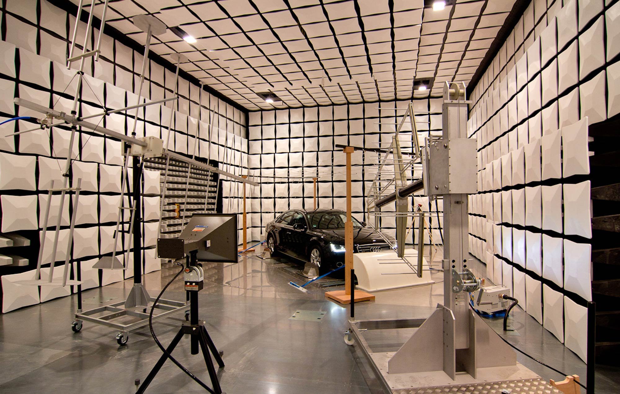
IEC 61000-4-21: “Testing and measurement techniques–Reverberation chamber test methods”
IEC 61000-4-21 aims to standardize radiated testing (both emissions and immunity/susceptibility) in reverb chambers. This includes testing for shielding effectiveness.
IEC 61000-4-21 doesn’t give any pass/fail criteria; it is solely aimed at standardizing radiated test methods conducted in reverb chambers. It was originally published in 2003 and last revised in 2011. You can purchase a copy here.
TIP:
Whenever possible, consider testing in a reverb chamber to save test time. Particularly for automotive testing, you don’t have to move the test object to illuminate three different orientations, since in reverb testing it will be hit from all angles. This is also a better correspondence to real-world conditions; in the automotive industry I ran into a few cases where a unit that passed ALSE testing failed during vehicle testing; the unit was then re-tested in reverb and failed there. It’s always better to troubleshoot at the module level than at the platform level.
This is one of those standards where the meat of the technical content is in the Annexes, so I’m listing them here:
Annex A (informative) Reverberation chamber overview
Annex B (normative) Chamber calibration for mode-tuning
Annex C (normative) Chamber calibration for mode-stirring
Annex D (normative) Radiated immunity tests
Annex E (normative) Radiated emissions measurements
Annex F (informative) Shielding effectiveness measurements of cable assemblies,cables, connectors, waveguides and passive microwave components
Annex G (informative) Shielding effectiveness measurements of gaskets and materials
Annex H (informative) Shielding effectiveness measurements of enclosures
Annex I (informative) Antenna efficiency measurements
Annex J (informative) Direct evaluation of reverberation performance using field anisotropy and field inhomogeneity coefficients
“Informative” annexes have information and context that may be useful for the user, where “normative” annexes contain steps and procedures that must be followed to use the standard correctly.
The annexes provide a fairly clear and practical overview of reverb chamber testing, including the statistical math needed to properly setup the test environment and interpret measured data. It has details about tuner steps and field uniformity volume, as well as chamber loading and sampling requirements.

TIP:
I’d like to draw attention to Annex F, for measuring shielding effectiveness of cables. This is generally an excellent option for testing cables at high frequencies, and not otherwise covered in IEC 62153. However, the test method compares the power received by a shielded cable to that received by a reference antenna within the uniform field volume of the chamber (see below). This may overestimate the attenuation provided by the shield, since an unshielded cable may not have similar gain as the reference antenna. Although it requires an extra step and extra cable sample, it may be more representative of real-world conditions to test both a shielded and unshielded cable, then compare the power received by each instead of comparing to a tuned antenna.

IEC 62153: “Metallic communication cables test methods”
IEC 62153 is a collection of test methods for characterizing cable shields for EMI control.
I’ve been thinking a lot about shielding lately, both in the run-up to a couple of focused seminars and also as a member of the IEEE P2855 working group (our modest goal is to become the “Recommended Practices for the Electromagnetic Screening Effectiveness Characterization of Cable/Connector Assemblies (CCAs) in Frequency Range of DC to 40 GHz” by 2026). One of the standards that comes up a lot when you’re discussing test methods for evaluating cable shielding is IEC 62153 “Metallic communication cables test methods” and its sub-parts. You can purchase any sub-part individually. I’m including a list of all the sub-parts here, since it’s annoyingly hard to find in one place:
Part 1-1: Metallic communication cables test methods – Electrical – Measurement of the pulse/step return loss in the frequency domain using the Inverse Discrete Fourier Transformation (IDFT)
Part 1-2: Metallic communication cables test methods – Electrical – Reflection Measurement
Part 4-0: Metallic communication cable test methods – Electromagnetic compatibility (EMC) – Relationship between surface transfer impedance and screening attenuation, recommended limits
Part 4-1: Metallic communication cable test methods – Electromagnetic compatibility (EMC) – Introduction to electromagnetic (EMC) screening measurements
Part 4-2: Metallic communication cable test methods – Electromagnetic compatibility (EMC) – Screening and coupling attenuation – Injection clamp method
Part 4-3: Metallic communication cable test methods – Electromagnetic compatibility (EMC) – Surface transfer impedance – Triaxial method
Part 4-4: Metallic communication cable test methods – Electromagnetic compatibility (EMC) – Shielded screening attenuation, test method for measuring of the screening attenuation as up to and above 3 GHz
Part 4-5: Metallic communication cables test methods – Electromagnetic compatibility (EMC) – Coupling or screening attenuation – Absorbing clamp method
Part 4-6: Metallic communication cable test methods – Electromagnetic compatibility (EMC) – Surface transfer impedance – Line injection method
Part 4-7: Metallic communication cable test methods – Electromagnetic compatibility (EMC) – Test method for measuring the transfer impedance and the screening – or the coupling attenuation – Tube in tube method
Part 4-8: Metallic communication cable test methods – Electromagnetic compatibility (EMC) – Capacitive coupling admittance
Part 4-9: Metallic communication cable test methods – Electromagnetic compatibility (EMC) – Coupling attenuation of screened balanced cables, triaxial method
Part 4-10: Metallic communication cable test methods – Electromagnetic compatibility (EMC) – Shielded screening attenuation test method for measuring the screening effectiveness of feed-throughs and electromagnetic gaskets double coaxial method
Part 4-11: Metallic communication cable test methods – Electromagnetic compatibility (EMC) – Coupling attenuation or screening attenuation of patch cords, coaxial cable assemblies, pre-connectorized cables – Absorbing clamp method
Part 4-12: Metallic communication cable test methods – Electromagnetic compatibility (EMC) – Coupling attenuation or screening attenuation of connecting hardware – Absorbing clamp method
Part 4-13: Metallic communication cable test methods – Electromagnetic compatibility (EMC) – Coupling attenuation of links and channels (laboratory conditions) – Absorbing clamp method
Part 4-14: Metallic communication cable test methods – Electromagnetic compatibility (EMC) – Coupling attenuation of cable assemblies (Field conditions) absorbing clamp method
Part 4-15: Metallic cables and other passive components test methods - Electromagnetic compatibility (EMC) - Test method for measuring transfer impedance and screening attenuation - or coupling attenuation with triaxial cell
Part 4-16: Metallic cables and other passive components test methods - Electromagnetic compatibility (EMC) - Extension of the frequency range to higher frequencies for transfer impedance and to lower frequencies for screening attenuation measurements using the triaxial set-up
Part 4-17: Metallic cables and other passive components - Electromagnetic compatibility (EMC) - Reduction Factor
Probably the most often cited sub-part is 4-3 on the triaxial method for measuring surface transfer impedance. Although it is less rigorous, my favorite method due to its flexibility and intuitive nature is 4-6, the line injection method.
TIP:
Keep a close eye on exactly what value is being measured in each test setup. While they are all closely related, transfer impedance, transfer admittance, screening attenuation, coupling attenuation, etc. are different in important ways. Likewise, when comparing shield characterizations between different vendors, understand what values they’re displaying and how those were measured. It may not be straightforward to compare values between vendors if they’re different measurands or derived using different test methods.
Although it’s less commonly used, give some consideration to the methods using absorbing clamps. My favorite, GSFC-STD-7000B, Section 2.5.3.3.2.1 has arguments in favor of using absorbing clamps for the frequency range 30 - 200 MHz that I found quite convincing.
IEC 62153 is not the only place to go looking for cable shielding test methods–IEC 61000-4-21 describes a method using reverb chambers, which I hope to write about soon, and eventually we hope IEEE P2855 will become a go-to document. However, if you’re looking to understand the details of some of the most common test methods, 62153 is a very good starting point.
BCI Testing: MIL-STD-461 CS114, RTCA DO160 Sec 20, and ISO 11452-4
Bulk Current Injection (BCI) testing is one of the best ways to ensure that operations will not be interrupted by low frequency noise via either radiated or crosstalk mechanisms of interference.
All Bulk Current Injection (BCI) tests are addressing the same risk: given a relatively long cable run mounted relatively close to conductive structure (vehicle chassis), the cabling can pick up electromagnetic noise from the surrounding environment. Cabling is especially good at doing this at lower frequencies, below 200-ish MHz. Various sources can be: crosstalk from co-routed cabling, noise from on-board RF transmitters, or noise from the external environment (radars, comms, HIRF, etc.). At higher frequencies, the risk is addressed by testing radiated susceptibility/immunity (e.g. RS103) in a semi-anechoic or reverb chamber. However there are drawbacks to that approach at lower frequencies: the longer distances of radiated testing doesn’t represent the crosstalk risk; reverb chambers are harder to spec at lower frequencies; radiated testing at 1 m is in the near field at lower frequencies, which can lead to a lack of replicability. Additionally, BCI testing can be done in a shield room instead of a more specialized (and often harder to schedule) ALSE or reverb chamber.
Thus BCI testing, where current is directly induced in the cable under test (CUT), is generally preferable below 200 MHz. There are three comparable standards that do this for defense, aerospace, and automotive industries that are worth examining:
MIL-STD-461G, CS114 (Defense and aerospace)
RTCA DO160, Section 20 (Civilian aircraft)
ISO 11452-4 (Automotive)
Differences between the three can be seen immediately from their frequency ranges and maximum induced current levels:
CS114: 10 kHz - 200 MHz, up to 109 dBuA
DO160: 10 kHz - 400 MHz, up to 109 dBuA
ISO 11452-4: 1 MHz - 400 MHz, up to 100 dBuA
DO160 mentions specifically that their frequency range is meant to overlap with their radiated susceptibility testing range, which starts at 100 MHz. ISO, focused on the automotive industry, doesn’t have as many strong threats in the kHz range (although given the increasing prevalence of HV systems in EVs switching in the kHz range, I wonder if this will change in the future).
Another thing to compare is the maximum amplitudes. MIL-STD-461G has a good rule of thumb that for wiring suspended 5 cm above a ground plane (as is specified in all the test testups), an incident E-field of 1 V/m will result in 1.5 mA of induced current. CS114 and DO160 have maximum levels of 109 dBuA, equivalent to 300 mA and assuming a maximum threat of 200 V/m. In both cases, HIRF (high intensity radiated field) is one of the driving concerns. If we apply the same formula to ISO 11452-4, we get an incident field of 67 V/m. This is a bit odd because the maximum vehicle level radiated immunity test in this frequency range goes up to 100 V/m, but there may be a presumption that the vehicle chassis provides some level of shielding to the unit.
The other thing to consider is the modulation of the injected current and the dwell times. All methods recommend dwelling for the response time of the unit under test (UUT) but have different minimums:
CS114: Amplitude modulated (AM) only, dwell time 3 sec
DO160: Both AM and continuous wave (CW), dwell time 1 sec
ISO 11452-4: Both AM and CW, dwell time 1 sec
Generally speaking a unit tested to DO160 BCI would be considered equivalent to one tested to CS114, but the different dwell times means there’s a small chance the DO160 test could miss something, while the fact that CS114 doesn’t cover 200 - 400 MHz means there’s a small chance something could be missed there.
In other respects, the test setups between the three are generally identical. They all have cables suspended 5 cm above a ground plane, with a monitor probe in addition to the injection probe during testing. They test cable bundles per connector, and if it is known that chassis will be used for current return the ground lead is excluded from the cable bundle. For CS114 and DO160, if there are cables with redundant purposes they should all be subjected to the BCI stimulus simultaneously; this situation generally does not arise on automotive modules.
TIP:
To save time and hassle later, test all cables unshielded but have a shielded version ready to swap in if there’s a serious failure. Especially on aerospace projects it is not uncommon to spec that all cables will be shielded and to do EMC testing that way–then later in the project to ditch the shielding for cost/weight purposes, rendering the earlier EMC testing meaningless. Testing without shielding gives you good confidence that the unit will be OK if shields are removed, or it will give you hard data to show that shields are necessary.
TIP:
GSFC-STD-7000b (as usual) has some excellent additional information on this test method in Section 2.5.3.3.6, which expands on some fundamental aspects beyond what you’ll find in the MIL-STD-461 appendices.
ESD: IEC 61000-4-2, MIL-STD-461 CS118, ISO 10605, et. al.
Several standards cover ESD testing in similar ways. This article gives an overview plus places to look for additional guidance and alternate discharge models.
The basis for most ESD (electrostatic discharge) tests comes from IEC 61000-4-2, “Testing and measurement techniques–Electrostatic discharge immunity test”. The active 2008 version can be purchased here, with a new version expected in 2025. ISO 10605, “Road vehicles — Test methods for electrical disturbances from electrostatic discharge” (purchase 2023 version here) adopted the test method for the automotive industry. MIL-STD-461 included ESD testing for the first time with Rev G (freely available here) with the CS118 test method–and it looked pretty familiar. See comparisons below.


TIP:
If you have questions about ISO10605 or IEC 61000-4-2, you can see if there are answers in the freely available MIL-STD-461G CS118 or related appendix (Section A.5.16) before purchasing from IEC or ISO.
Testing is specified for units that are powered off (representing the danger from discharge when being handled or installed) and when turned on (representing threats present in its operating environment). They also include air and contact discharge, with air discharge generally being more severe. Contact discharge is mating two conductive objects at different potentials together and seeing the surge of charge transfer. Air discharge is when you reach for a metal doorknob on a dry/cold day and feel an actual spark just before you touch the door. Maximum testing voltages should be adjusted based on the expected operating conditions (how often humans interact with the unit, if it is installed in a humidity-controlled environment, etc.).
TIP:
ANSI C63.16, “Guide for Electrostatic Discharge Test Methodologies and Acceptance Criteria for Electronic Equipment”, is an available guidance document for ESD testing (the 2016 version is available for purchase here; a new version has been drafted and is currently going through ANSI approvals). It gives additional context
Almost all ESD test standards and commercially available ESD test guns/simulators base their waveforms off the human body model (HBM). The CS118 version is below.

However, there are cases where the main threat does not come from human interaction. Generally speaking the industries have determined that testing based on the HBM is adequate to identify most hardware weaknesses to ESD (although the ANSI C63.16 working group will tell that’s definitely not 100% true). I was once looking into a case where the main threat to a satellite orbiting in Low Earth Orbit was definitely going to be spacecraft charging, and did some research to see if there were other standard models available.
TIP:
The only one I was able to find was from an outdated military standard, MIL-STD-1541A (1987) (freely available here). You can see an alternate discharge model below, and the document has information about ways to vary different parts of the circuit to address different threat waveforms.
MIL-STD-331D (download here) includes circuit values for helicopter-based discharges for fuzing systems and ignition protection devices as well, to be inserted into a more traditional IEC 61000-4-2 circuit setup. Appendix A.5.8.3.2 of MIL-STD-464D also has information on helicopter-borne discharges & ordnance.

CISPR 11: “Industrial, scientific and medical equipment – Radio-frequency disturbance characteristics – Limits and methods of measurement”
This is an important standard limiting radiated and conducted emissions from non-consumer electronics, which have different concerns in terms of operating environments than tests such as FCC/ANI C63.4.
Like most CISPR standards, CISPR 11 aims to control the unintentional emission of RF energy from equipment, in this case industrial, scientific and medical (ISM) equipment. These are units designed to operate in more restricted areas than general consumer electronics. They divide ISM equipment into two classes, Class A and Class B, where Class B equipment may be used in a residential setting. However its main concern is higher power equipment, such as arc welders, that are not found in casual use. It also distinguishes between Groups 1 and 2, where Group 2 equipment includes intentional generation of RF signals. A newly revised version of CISPR 11 was published in 2024 and can be purchased here. It informs IEC 60601-1-2 on medical equipment.
CISPR 11 looks at both conducted and radiated emissions, although as Henry Ott pointed out years ago, in these cases conducted emissions tests are really radiated emissions controls in disguise. Section 6 lays out the emissions limits for different equipment in different situations, and Sections 7 and 8 concern measurements methods. Limits start at 150 kHz and, depending on application, go up to 18 GHz. They are generally expressed as both Average and Quasi Peak levels. It refers back to CISPR 16 for most measurement equipment specifications.
The test methods of CISPR 11 acknowledge that the equipment that falls under this standard may be considerably more complex than the kinds of modules you might test under MIL-STD-461 or CISPR 25. Hence it allows Class A equipment to be tested in situ (on site) if needed. As such, it has a different approach to, for instance, characterizing ambient noise levels. It also describes different kinds of LISN/Artificial Network configurations. It spends quite a bit of time concerning cable arrangements, which can be critical for accurate, repeatable measurements.
Some useful information in the appendices (Always Read the Appendices!) includes protection and concerns when using spectrum analyzers around ISM and other potentially higher power equipment; ways to handle existing RF transmissions in the environment when you can’t use a shield room; and worldwide frequency allocations and particular safety-related bands that should be protected.
TIP:
Some limits changed in the 2024 revision, mostly to cover newer equipment configurations. It also now addresses industrial robots specifically.
ANSI C63.16: “Guide for Electrostatic Discharge Test Methodologies and Acceptance Criteria for Electronic Equipment”
This is a guidance document for ESD testing that helps the users of IEC 61000-4-2 (as well as ISO 10605 and MIL-STD-461 CS118)
ANSI C63.16 is a useful document meant to provide guidance for engineers and technicians conducting ESD testing to IEC 61000-4-2. Which means it is also useful for people testing to ISO 10605 and MIL-STD-461 CS118 by extension, since those documents are close to identical with the IEC standard. The 2016 version of C63.16 can be purchased here, but you might want to wait. A new version is expected to be published in late 2024/early 2025, which will have several technically substantial updates. I’m on the working group for this revision, so it’s near and dear to my heart.
Some of the topics addressed in C63.16:
Climate conditions during testing
The use of air vs. contact discharges
Test setups
Considerations for the ESD gun return cable
Considerations for the bleed resistors (in the revision, issues of degradation over time are raised)
Test procedures
Selecting test points
Handling large EUTs or those with complex peripheral arrangements
Approach speed for air discharges
In situ testing
Pin discharges
A lot of the guidance found in this document is based on decades worth of lessons learned. It points out things that are easy to miss until they go wrong.
TIP:
There have been a large number of cases where customers report issues in the field that hadn’t been caught and can’t be replicated in the lab. C63.16 aims to add to the minimum number of tests and test conditions called for in IEC 61000-4-2 in order to reduce these situations.
TIP:
The new revision contains an extensive discussion of relative humidity. Humidity can vary dramatically between indoors and outdoors, as well as different locations within a building, so knowing what the conditions are specifically where testing is occuring helps with repeatability. ESD events, in particular air discharges, are known to be sensitive to humidity conditions. On many occasions, the fact that equipment is used in environments far outside the 30 - 60% relative humidity called for by IEC 61000-4-2 is the cause for disconnects between field issues and lab testing as noted above.
NASA-HDBK-4001: “Electrical Grounding Architecture for Unmanned Spacecraft”
This NASA guidance document has conceptual and practical information and recommendations for people designing grounding for complex systems.
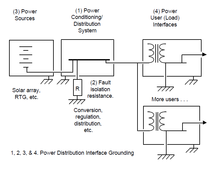
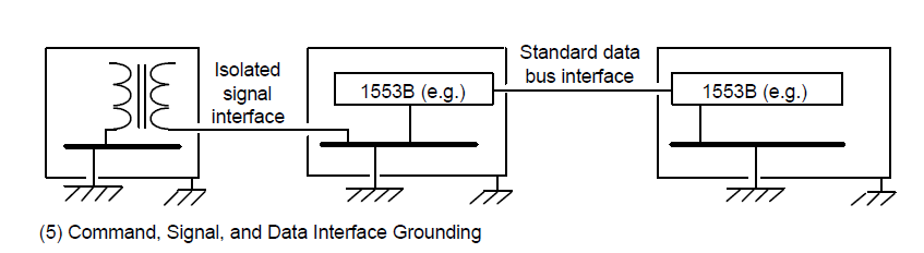
I have long complained that the word “grounding” means too many things in electrical engineering. It can mean (1) A connection to Earth/dirt; (2) A current return path; or (3) A voltage/potential reference. At least in this publicly available NASA document (free to download here) we don’t have to worry about meaning #1–there’s no way we’re connecting a spacecraft to the dirt back on Earth. This guidance document from 1998 has useful information for anyone looking at implementing “grounding” (both in terms of (2) and (3)) on a mobile platform with largely conductive structure.
Although fairly concise at 29 pages, 4001 covers a lot of ground (pardon the pun). It acknowledges up front that there’s no single “correct” grounding approach, and it covers which design considerations are most important in designing a grounding architecture. It approaches grounding design from the systems perspective, largely looking at the connections between modules. I find the conceptual diagrams to be particularly helpful, such as the ones highlighting power distribution and signals below.
Topics addressed in NASA-HDBK-4001:
Ground isolation and ground loops
Different requirements for different frequencies of interest
Single point ground (SPG or “star” grounding) vs. multiple point ground
Bleed resistors
Bonding
Different requirements depending on platform size
Grounding for sensors, RF systems, pyro devices, etc.
Ground fault isolation
It also shows a fascinating example in the appendix drawn from the Cassini mission of what this kind of grounding architecture looks like on a large and complex spacecraft
TIP:
NASA-HDBK-4001 calls out MIL-B-5087B for bonding guidance, but today the recommendation would be to refer to NASA-HDBK-4003. The latter document had not yet been written in 1998 when 4001 was first published.
Designing in appropriate grounding for complex systems is such a large topic that it’s not captured in many other standards. While its main applicability is to a very specific set of hardware, NASA-HDBK-4001 is a good starting point for people outside of NASA and outside of aerospace who are having to make grounding-related design decisions.
IEEE 299 and 299.1 on Measuring the Shielding Effectiveness of Enclosures
These two IEEE standards look at shielding effectiveness measurements for enclosures both large and small.
IEEE 299 is titled “Standard Method for Measuring the Effectiveness of Electromagnetic Shielding Enclosures” and is by far the most widely used IEEE standard sponsored by the EMC Society. IEEE 299.1 is the “Standard Method for Measuring the Shielding Effectiveness of Enclosures and Boxes Having All Dimensions between 0.1 m and 2 m”. It is also widely accessed. While both of these standards are considered currently “inactive”, you can purchase 299 (here) and 299.1 (here) from the IEEE.
IEEE 299 is a relatively straightforward standard, with 39 pages of technical content of which 13 are found in five informative annexes. IEEE 299.1 is rather more complex, since it deals with situations where enclosure dimensions are small compared to the wavelengths of the RF fields and frequencies of interest. The copy I have has 44 pages in the main document, plus another 38 pages in 12 informative annexes.
Dealing with enclosures where the smallest dimension is 2 m or greater, IEEE 299 defines test methods from 9 kHz - 18 GHz, extendable down to 50 Hz and up to 100 GHz. The table below shows the recommended antennas for different frequency ranges.

Depending on the frequency range, the measurand might be voltage, H field, E field, or power. After that, shielding effectiveness can be calculated in a straightforward way, comparing the value without the enclosure (Value1) to the value with the enclosure (Value2):
[linear values] SE = 20 log10 (Value1/Value2) (or 10 * log10 when comparing power)
Or
[dB values] SE = Value1 - Value2
The measurements involved aren’t trivial, but with enough space to place equipment the procedures are relatively simple.
IEEE 299.1 has a harder job, since the smaller dimensions seriously constrain test equipment and configurations. It officially covers the same frequency range as 299. The standard divides itself into two sections, one covering 0.75 - 2 m and the other 0.1 - 0.75 m. At this point, testing within a reverb chamber becomes a much more attractive option than in IEEE 299, and the standard spends a lot of time on those methods (see also IEC 61000-4-21). Data collected this way takes a little more math to interpret correctly, due to the statistical nature of reverb chamber measurements. The standard as currently written feels somewhat incomplete and refers to continuing research in the area of measurements of physically and electrically small enclosures.
Both of these standards have been approved to move forward with renewal by the EMC Society and will be moving to IEEE Standards Association approval in the Fall of 2024. After that approval comes through a working group will be formed under the leadership of Dr. Davy Pissoort of KU Leuven. The expectation is that IEEE 299 will be renewed with only minor updates to the technical content, where 299.1 will require more extensive revisions. If you are interested in being involved in this effort, please contact me at standards@emcunited.com and I can put you in touch with Dr. Pissoort.
NASA-STD-4003: “Electrical Bonding for NASA Launch Vehicles, Spacecraft, Payloads, and Flight Equipment”
NASA-STD-4003 is the rare EMC standard that covers electrical bonding in a comprehensive way.
NASA-STD-4003 is unusual for its focus on bonding–which is more of a concern for aerospace projects than for most others. If you look in Henry Ott’s classic EMC Engineering or Michel Mardiguian’s useful Controlling Radiated Emissions by Design, you won’t see bonding mentioned much. But for aerospace, given its severe electromagnetic environments (lightning, plasma charging, EMP, etc.), bonding is critical. Following the guidance of NASA-STD-4003 gets you a long way to meeting the requirements of MIL-STD-464. 4003 can be freely downloaded here.The most recent revision is Rev A with changes, dated January 2016.
4003 separates bonds into different categories depending on their purpose. There are five categories, as seen in the main summary table below.

This table illustrates how broadly applicable this document is: although NASA spacecraft rarely use chassis for power return, the Class C bond category covers exactly that case–useful for aircraft and other vehicles types, beyond just space missions.
One challenge with NASA-STD-4003 is that some of the numbers it has in the summary table have been imposed as hard-and-fast requirements without an understanding of where those numbers come from and how they can be tailored to particular programs.
One example is “2.5 mOhms” for RF and lightning. Lightning and RF currents both have high frequency components. We’re trying to establish a low impedance path for these currents, but 2.5 mOhms is a DC resistance value. The reason for this is simply that it is MUCH easier to measure the DC resistance of an installed bond with a milliohm meter than it is to measure the high frequency impedance of a joint. IN GENERAL, if you can establish a 2.5 mOhm bond upon installation, you have likely also created a low impedance joint, since you have to have excellent metal-to-metal contact to get 2.5 mOhm at DC. But that doesn’t mean that if you have an 8 mOhm joint that your hardware will fail; it means you need to put more thought into the specific mission parameters are driving the need for bonding at that joint.
TIP:
Bonding measurements per NASA-STD-4003 are taken per joint, not on a point-to-point basis. Example: I have a cable harness going from one metal box to another with an overbraid shield installed, connected to MIL-STD-38999 connector backshells on both ends. Let’s say the bonding requirement for this particular shield is deemed to be the 2.5 mOhm Class R category. In this case, we do not need the measurement from box to box to be less than or equal to 2.5 mOhm. Here are the measurement requirements in that case:
Box A to connector backshell A < 2.5 mOhm
Connector backshell A to shield < 2.5 mOhm
Shield to connector backshell B < 2.5 mOhm
Connector backshell B to Box B < 2.5 mOhm
OR: Box A to Box B < 10 mOhm
TIP:
The origin of the 2.5 mOhm requirement goes back at least 70 years, and derives from the need to keep the voltage developed across any single joint under 500 V in the event of a 200 kA lightning strike. Nothing in its origin relates to controlling the impedance of structure for RF systems. Even the 500 V number is somewhat arbitrary and likely stems from the need to prevent sparking between structural elements surrounding fuel tanks. The 2.5 mOhm number has been adopted because it is a conservative value that is easy to measure and, if met, generally ensures proper system functioning. However, for new systems, and particularly any systems using novel materials such as composite airframes, new analysis should be done to determine what value of Class R bonding is needed for that particular project. This is a case where detailed simulations can give good answers early in the program and help drive reasonable requirements development.
One excellent way I’ve seen to capture bonding information is in a diagram such as the example below. In it you see places where different metallic elements join together. At each joint there’s a circle specifying the purpose of that particular joint. So from one box to structure a joint is necessary to carry fault current. Between two different kinds of structural panels, Class L bonds are needed, and to ensure proper functioning of an RF system Class R bonds are needed. In one area where a joint is needed both for lightning protection and for RF performance, a hybrid joint is specified. (In this case, the lowest bond value requirement is imposed.) This kind of diagram gives an at-a-glance image for the people setting structural bonding requirements, as well as a quick reference for people monitoring installations. It also helps ensure that if bonding requirements change later in the program, a relaxation of the Class L bond requirement (for example), won’t be blindly applied to a joint that has both a Class L and Class R function.

RTCA DO-160: “Environmental Conditions and Test Procedures for Airborne Equipment”
RTCA DO-160 is critical for qualifying electronics modules for use on aircraft.
RTCA DO-160 is key for getting electronics modules tested in order to ensure proper operation and support certification of aircraft. The current Rev is G and can be purchased here. Its history traces back to 1958, about the same time the precursors to MIL-STD-461 were coming into existence. It follows the same general principles as many MIL-STD-461-derived standards: test individual units very thoroughly, and when you integrate them into a larger system you have a good chance that will operate together successfully. In DO-160, EMC-related topics are a subset of a larger realm of environmental testing, including thermal, humidity, shock & vibe, sand & dust, salt spray, etc. Sections 16 - 23, plus 25, are the ones with the most EMC/E3 impact.
Section 16 specifies “Power Input” and can be thought of as a power quality spec. It controls things like normal operating voltages, both AC and DC, normal transients, ripple voltages, phase imbalance for AC power, and abnormal conditions as well. It has more in common with MIL-STD-704 than 461 or 464. This section assumes the equipment under test (EUT) is getting power in one of the following forms: 14, 28, or 270 Vdc, or 115 or 230 Vrms AC at 400 Hz.
Section 17 is for “Voltage Spike” testing. This is most similar to MIL-STD-461 CS06/CS106 testing, which was removed from the latest 461 Rev G. It can be found in the older versions of 461, as well as in GSFC-STD-7000.
Section 18, “Audio Frequency Conducted Susceptibility”. This is closely related to MIL-STD-461 CS101, which can be a tricky test to execute.
TIP:
Figure 18-1 of DO-160G shows an optional current monitor as part of the test setup. Always use this if you have the equipment–it gives you a lot of additional information for not a lot of extra effort. In particular it gives you the ability to calculate how the input impedance of the EUT is changing over frequency.
Section 19 covers “Induced Signal Susceptibility”. This doesn’t have a direct MIL-STD-461 analogue, but in general it is looking for susceptibility to low frequency stimulus induced in signal lines, as opposed to Section 18 focusing on power lines.
Section 20, “RF Susceptibility (Radiated and Conducted)” covers similar test methods to MIL-STD-461 CS114 and RS103. The radiated test includes both semi-anechoic and reverb methods.
Section 21, “Emission of RF Energy”, covers similar test methods to MIL-STD-461 CE102 and RE102. As in Section 20, the radiated test includes both ALSE and reverb methods.
TIP:
Use reverb testing whenever possible to save time. DO-160G Section 20 has excellent information about the mathematical and statistical techniques needed to ensure a chamber is set up correctly. The math is scarier, but there’s a significant savings in terms of testing time-in-chamber.
Sections 22 and 23 cover lightning testing (“Lightning Induced Transient Susceptibility” and “Lightning Direct Effects”). These share a lot of heritage with MIL-STD-464 as electromagnetic environmental effects tests. Section 25 covers ESD, and like most ESD specs basically follows IEC 61000-4-2.
TIP:
One of the things that separates DO-160 from other standards is the use of alphanumeric codes to describe the EUT and the applicable tests. Whenever you pin down a letter/number designation that applies to your EUT, write it down somewhere. Otherwise you’ll spend a lot of time flipping back and forth across many pages trying to find the right code again.
SpaceX Payload User’s Guides
SpaceX User’s Guides are particularly useful in summarizing EM environments for launch and ground handling.
SpaceX provides “User’s Guides” (Payload User’s Guides, or PUGs) for payloads going on Falcon 9, Falcon Heavy, or taking advantage of its Rideshare program. They’re all free to download from SpaceX. These are fairly comprehensive documents, including mission planning timelines and different environments: thermal, shock/vibe, pressure, etc., along with necessary mechanical and electrical interface specs. For our purposes, the section within “Environments” on “Electromagnetic” can be useful beyond only specific payload missions.
The purpose of this section is to let the user know what electromagnetic environments it might be exposed to, and also how it must limit its emissions in order to protect the RF and avionics systems of the launch vehicle. The limits are, on the whole, more lenient than the default limits found in MIL-STD-461, both for emissions and susceptibility, and can be very useful for tailoring EMC requirements and testing.
What I find particularly helpful is the set of limits in the image below. This is an envelope of the worst-case EM radiation environment between both the Eastern and Western launch ranges where SpaceX operates. (Presumably when Starship gets its own User’s Guide, the environment for the Texas base will be included as well.) This is incredibly helpful for planning what levels a piece of equipment should be robust enough to handle during all phases of operations leading up to launch: shipping, ground handling and checkouts, stacked and awaiting launch, as well as launch itself. This helps inform EMC radiated susceptibility test levels with a lot more granularity than the 20 V/m level set by MIL-STD-461, and is information that used to be hard to find.

CISPR 16: “Specification for radio disturbance and immunity measuring apparatus and methods”
CISPR 16 is one of the key standards governing the measurement instrumentation used in EMC testing.
CISPR 16 is a core standard governing the measurement instruments used in many forms of EMC testing, both for other CISPR standards such as CISPR 12, but ISO and others as well. It is generally harmonized with ANSI C63.2, which is the instrumentation standards called out by ANSI C63.4, which is the test method required for FCC testing. (The tangled knots we weave in standards!) The most recent official version is from 2019, and it can be purchased here. It generally covers the frequency range 9 kHz - 18 GHz, although it can be extended higher.
This standard gets deep into the weeds for the details of how measurements are taken, both for immunity/susceptibility and for emissions. For instance, this is one of the few places where the mathematical definitions of how quasi-peak measurements are weighted are written down.
As with other IEC/CISPR documents, there are a lot of sub-parts of CISPR 16:

Having official copies of these documents is critical if you are an instrument manufacturer or certified test lab.
TIP:
CISPR 16 explains the differences between spectrum analyzers and EMI receivers and treats them separately. This is a subtle difference since they both give the same apparent output to the casual observer (voltage amplitude vs. frequency). If you are using this equipment it is important to know the strengths and weaknesses of both and understand which one you’re working with.
ICNIRP: “ICNIRP GUIDELINES FOR LIMITING EXPOSURE TO ELECTROMAGNETIC FIELDS (100 KHZ TO 300 GHZ)”
ICNIRP 2020 Guidelines help determine limits on electromagnetic fields for human protection.
ICNIRP (often pronounced “ick-nerp”) is the International Commission on Non-Ionizing Radiation Protection. They are a global research group that has been studying the safety implications of electromagnetic radiation (as opposed to nuclear ionizing radiation, e.g. Chernobyl), from DC to 300 GHz, since 1992. (The commission was chartered in 1992, but includes research and researchers going back to 1973.) They publish a wide variety of freely available guidelines, statements, and papers on their website. The most recent major guideline document for RF energy (100 kHz - 300 GHz) was published in 2020 and can be downloaded here.
ICNIRP has published major guidelines on safe levels of electromagnetic energy for both the general public and specialist workers in 1998 and 2020. It has had a significant influence on related standards such as ANSI C95.1. The two main categories of potential EM field/human body interactions with RF fields are nerve stimulation (more prevalent at lower frequencies) and tissue heating. Probably the table that product designers will reference the most is Table 2 on basic restrictions (2020), as seen below.

SAR = specific absorption rate, which is the key metric when looking at exposure from devices such as cell phones.
After this table there is a lot more information on refining these levels for different scenarios. And as always, there is extremely useful information contained in the appendices.
There is a 2010 document that covers 1 Hz - 100 kHz for low-frequency effects and exposure to magnetic fields. There’s also a 2014 document with guidance on fields that vary at less than 1 Hz.
TIP:
In general, the exposure guidelines have relaxed over time, as additional research allows the commission to refine its knowledge of human effects and move away from worst-case assumptions. However, since many medical devices are still in circulation that were built assuming the stricter guidelines from 1998, if you need to set default limits, you should use the 1998 document as your guidance.
TIP:
ICNIRP has gotten drawn into numerous controversies and public panic about high voltage power lines, cell phones, 5G specifically, and other topics. If you have concerns about any of these topics, I highly recommend you go through their meticulously researched and documented (and freely available) publications on your specific concerns. I have learned a lot about EM interactions with human bodies through reading their research.