Start Here:
NASA-HDBK-4002: “Mitigating In-Space Charging Effects–A Guideline”
NASA-HDBK-4002 is valuable for space missions concerned with spacecraft charging effects.
As spacecraft orbit the Earth, they are constantly interacting with the environment around them (falling less into the “EMC” category and more into the “electromagnetic environmental effects (E3)” category). While we think of space as a vacuum, depending on your orbit and altitude the craft will interact with different densities of particles with different energetic properties. NASA-HDBK-4002 is a valuable guide for dealing with the effects of these interactions. The current revision is “B” as of 2022, and you can download a publicly available copy here.
Possibly one of the most useful parts of NASA-HDBK-4002 is Figure 1, showing the risk of spacecraft charging per orbital altitude and range of latitudes covered (see below). This gives you a first indication of how much you need to worry about this threat given your mission profile

Rev B has a number of useful updates, including the incorporation of all the new data that’s come in since the last revision in 2017. A similar graph in Figure 2, relating charging risk for orbital inclination and altitude, is vastly more granular than the equivalent graph in 2017, reflecting the rapidly growing body of knowledge in this area.
There are two main spacecraft charging risks. The first is when surfaces charge up to high potentials relative to other surfaces or relative to the space plasma surrounding the vehicle. When this occurs you can have significant ESD events. Solar arrays are particularly susceptible to this risk, and 4002 has some sobering pictures, as shown below.

A more insidious threat is that high energy electrons can penetrate the chassis and even electronics enclosures and bury themselves in printed circuit boards, charging them up over time and potentially leading to internal damage.
There are a lot of nuances involved in analyzing these risks, including the difference in charging when a satellite is in shadow vs. in sunlight, the distribution of high energy electrons in different orbital regions, the different materials and thicknesses involved, etc. While not a comprehensive textbook, the 209 pages of 4002 Rev B give a good overview of the different factors involved and how they should drive design decisions.
TIP:
As I’ve mentioned before, most ESD testing is based on a human body model of electrostatic discharge. There’s an older military standard that addresses how to set up a test for different discharge profiles, MIL-STD-1541. NASA-HDBK-4002B takes that MIL-STD-1541 setup and customizes it for spacecraft charging risks in Section 6.3.1.1, which may come in handy for others looking to represent non-human discharge threats.
If you are working in this area, there are a few other documents that you might want to have on hand:
NASA-STD-4005, “Low Earth Orbit Spacecraft Charging Design Standard”; this is a set of requirements for missions in common low-risk low earth orbits such as that occupied by the International Space Station
NASA-HDBK-4006, “Low Earth Orbit Spacecraft Charging Design Handbook”; this gives more context and guidance for how to meet the 4005 requirements
NASA-HDBK-4007, “Spacecraft High-Voltage Paschen and Corona Design Handbook”; covering ways to insulate and protect high voltage systems that may be subject to more severe risks over time
SLS-SPEC-159, “Cross-Program Design Specification for Natural Environments (DSNE)”; this broadly defines the environments you’ll see throughout the solar system, from the launch pad to GEO to Jupiter. This includes electromagnetic and plasma environments, but also thermal, gravitational, ionizing radiation, and more
NASA-HDBK-4001: “Electrical Grounding Architecture for Unmanned Spacecraft”
This NASA guidance document has conceptual and practical information and recommendations for people designing grounding for complex systems.
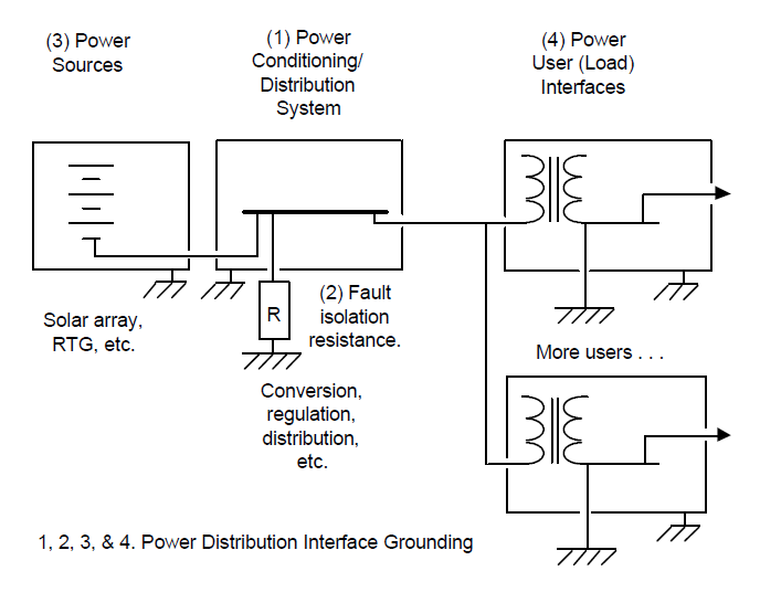
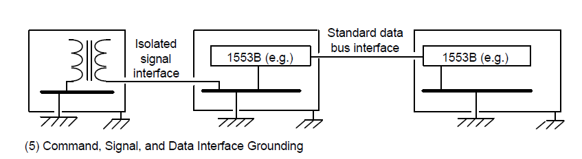
I have long complained that the word “grounding” means too many things in electrical engineering. It can mean (1) A connection to Earth/dirt; (2) A current return path; or (3) A voltage/potential reference. At least in this publicly available NASA document (free to download here) we don’t have to worry about meaning #1–there’s no way we’re connecting a spacecraft to the dirt back on Earth. This guidance document from 1998 has useful information for anyone looking at implementing “grounding” (both in terms of (2) and (3)) on a mobile platform with largely conductive structure.
Although fairly concise at 29 pages, 4001 covers a lot of ground (pardon the pun). It acknowledges up front that there’s no single “correct” grounding approach, and it covers which design considerations are most important in designing a grounding architecture. It approaches grounding design from the systems perspective, largely looking at the connections between modules. I find the conceptual diagrams to be particularly helpful, such as the ones highlighting power distribution and signals below.
Topics addressed in NASA-HDBK-4001:
Ground isolation and ground loops
Different requirements for different frequencies of interest
Single point ground (SPG or “star” grounding) vs. multiple point ground
Bleed resistors
Bonding
Different requirements depending on platform size
Grounding for sensors, RF systems, pyro devices, etc.
Ground fault isolation
It also shows a fascinating example in the appendix drawn from the Cassini mission of what this kind of grounding architecture looks like on a large and complex spacecraft
TIP:
NASA-HDBK-4001 calls out MIL-B-5087B for bonding guidance, but today the recommendation would be to refer to NASA-HDBK-4003. The latter document had not yet been written in 1998 when 4001 was first published.
Designing in appropriate grounding for complex systems is such a large topic that it’s not captured in many other standards. While its main applicability is to a very specific set of hardware, NASA-HDBK-4001 is a good starting point for people outside of NASA and outside of aerospace who are having to make grounding-related design decisions.
NASA-STD-4003: “Electrical Bonding for NASA Launch Vehicles, Spacecraft, Payloads, and Flight Equipment”
NASA-STD-4003 is the rare EMC standard that covers electrical bonding in a comprehensive way.
NASA-STD-4003 is unusual for its focus on bonding–which is more of a concern for aerospace projects than for most others. If you look in Henry Ott’s classic EMC Engineering or Michel Mardiguian’s useful Controlling Radiated Emissions by Design, you won’t see bonding mentioned much. But for aerospace, given its severe electromagnetic environments (lightning, plasma charging, EMP, etc.), bonding is critical. Following the guidance of NASA-STD-4003 gets you a long way to meeting the requirements of MIL-STD-464. 4003 can be freely downloaded here.The most recent revision is Rev A with changes, dated January 2016.
4003 separates bonds into different categories depending on their purpose. There are five categories, as seen in the main summary table below.

This table illustrates how broadly applicable this document is: although NASA spacecraft rarely use chassis for power return, the Class C bond category covers exactly that case–useful for aircraft and other vehicles types, beyond just space missions.
One challenge with NASA-STD-4003 is that some of the numbers it has in the summary table have been imposed as hard-and-fast requirements without an understanding of where those numbers come from and how they can be tailored to particular programs.
One example is “2.5 mOhms” for RF and lightning. Lightning and RF currents both have high frequency components. We’re trying to establish a low impedance path for these currents, but 2.5 mOhms is a DC resistance value. The reason for this is simply that it is MUCH easier to measure the DC resistance of an installed bond with a milliohm meter than it is to measure the high frequency impedance of a joint. IN GENERAL, if you can establish a 2.5 mOhm bond upon installation, you have likely also created a low impedance joint, since you have to have excellent metal-to-metal contact to get 2.5 mOhm at DC. But that doesn’t mean that if you have an 8 mOhm joint that your hardware will fail; it means you need to put more thought into the specific mission parameters are driving the need for bonding at that joint.
TIP:
Bonding measurements per NASA-STD-4003 are taken per joint, not on a point-to-point basis. Example: I have a cable harness going from one metal box to another with an overbraid shield installed, connected to MIL-STD-38999 connector backshells on both ends. Let’s say the bonding requirement for this particular shield is deemed to be the 2.5 mOhm Class R category. In this case, we do not need the measurement from box to box to be less than or equal to 2.5 mOhm. Here are the measurement requirements in that case:
Box A to connector backshell A < 2.5 mOhm
Connector backshell A to shield < 2.5 mOhm
Shield to connector backshell B < 2.5 mOhm
Connector backshell B to Box B < 2.5 mOhm
OR: Box A to Box B < 10 mOhm
TIP:
The origin of the 2.5 mOhm requirement goes back at least 70 years, and derives from the need to keep the voltage developed across any single joint under 500 V in the event of a 200 kA lightning strike. Nothing in its origin relates to controlling the impedance of structure for RF systems. Even the 500 V number is somewhat arbitrary and likely stems from the need to prevent sparking between structural elements surrounding fuel tanks. The 2.5 mOhm number has been adopted because it is a conservative value that is easy to measure and, if met, generally ensures proper system functioning. However, for new systems, and particularly any systems using novel materials such as composite airframes, new analysis should be done to determine what value of Class R bonding is needed for that particular project. This is a case where detailed simulations can give good answers early in the program and help drive reasonable requirements development.
One excellent way I’ve seen to capture bonding information is in a diagram such as the example below. In it you see places where different metallic elements join together. At each joint there’s a circle specifying the purpose of that particular joint. So from one box to structure a joint is necessary to carry fault current. Between two different kinds of structural panels, Class L bonds are needed, and to ensure proper functioning of an RF system Class R bonds are needed. In one area where a joint is needed both for lightning protection and for RF performance, a hybrid joint is specified. (In this case, the lowest bond value requirement is imposed.) This kind of diagram gives an at-a-glance image for the people setting structural bonding requirements, as well as a quick reference for people monitoring installations. It also helps ensure that if bonding requirements change later in the program, a relaxation of the Class L bond requirement (for example), won’t be blindly applied to a joint that has both a Class L and Class R function.

GSFC-STD-7000B: “General Environmental Verification Standard (GEVS) for GSFC Flight Programs and Projects”
GSFC-STD-7000B contains something like a version of MIL-STD-461 specifically tailored for small, metal chassis, science satellites
GSFC-STD-7000, affectionately known as GEVS, is a huge document covering a wide variety of environmental testing, including shock, vibe, thermal, etc. For our purposes we’re only concerned with Section 2.5 on EMC. Written by John McCloskey and Ken Javor, it is worth making sure to get Rev B. While both revisions have the same approach--tailoring MIL-STD-461 for the kind of missions most common at Goddard Space Flight Center--Rev B has a greatly expanded Section 2.5.3, which serves the same function as the appendices of MIL-STD-461. It is a wealth of additional information and context on each test method and how it came to be specifically tailored in this document. This is hands-down one of my favorite standards documents, and I refer to it even when I’m not working on Goddard or NASA programs. The document is freely and officially available here.
The tailoring in GEVS is based on certain assumptions that hold true for the most common GSFC programs:
Uncrewed satellites
Generally cubes, generally smaller than 2 meters on a side
They have metal chassis
They never use structure for current return
28 Vdc power bus, sourced from batteries and recharged from solar panels
The table below shows a summary of the requirements they arrived at, and a top-level comparison with MIL-STD-461.

TIP:
One thing that I appreciate is that it includes a test not found in MIL-STD-461, which is a common mode conducted emissions test. It’s found in Section 2.5.2.1.2. While MIL-STD-461 CE101 and CE102 have differential measurements taken from a LISN, this test uses a current probe to measure the common mode currents flowing on the cables--which is one of the prime indications of potential crosstalk or radiated emissions problems. It also has a method for extending the test range from 30 MHz up to 200 MHz using an absorbing clamp as described in CISPR 16-1-4. GEVS section 2.5.3.3.2.1 contains an extremely thorough and well-thought-out discussion of why absorbing clamps are appropriate at the higher frequencies, and it left me thoroughly convinced. For people in the automotive industry, the 30 - 200 MHz is particularly critical for EVs seeking to pass CISPR 12 testing, and the common mode, absorber clamp method may be a useful pre-compliance test for that purpose.
TIP:
Instead of the more commonly found 50 uH or 5 uH LISNs used in much MIL-STD-461 and automotive component testing, GEVS uses a 10,000 uF cap network. It’s worth reading the rationale in Section 2.5.3.2.2 (with related discussion in MIL-STD-461 Rev G Section A.4.3.6) to broaden your thinking about LISN/Artificial Network choice. For more on LISNs, see this post.