
Start Here:
IEC 61000-4-21: “Testing and measurement techniques–Reverberation chamber test methods”
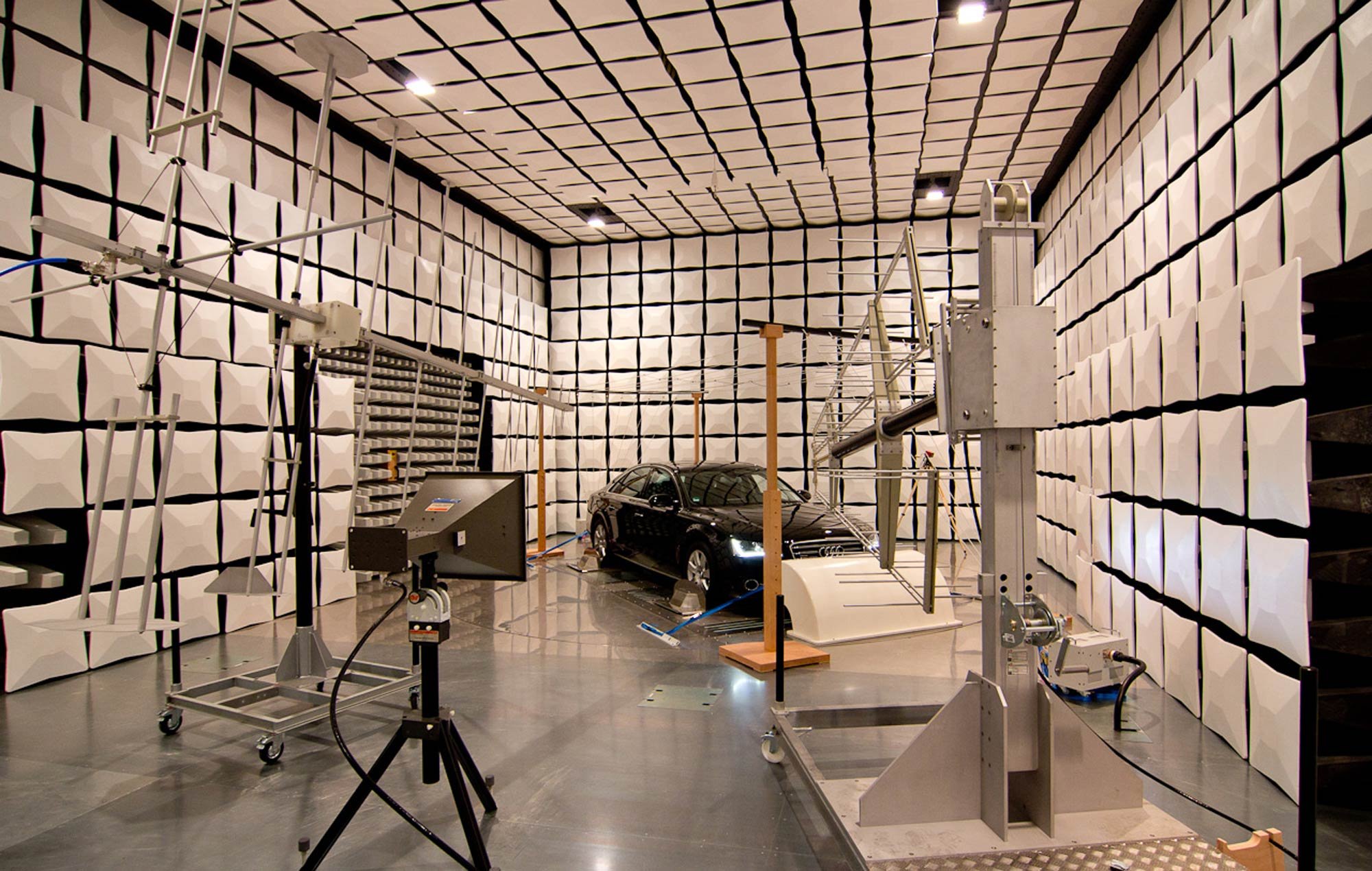
IEC 61000-4-21 aims to standardize radiated testing (both emissions and immunity/susceptibility) in reverb chambers. This includes testing for shielding effectiveness.
IEC 61000-4-21 doesn’t give any pass/fail criteria; it is solely aimed at standardizing radiated test methods conducted in reverb chambers. It was originally published in 2003 and last revised in 2011. You can purchase a copy here.
TIP:
Whenever possible, consider testing in a reverb chamber to save test time. Particularly for automotive testing, you don’t have to move the test object to illuminate three different orientations, since in reverb testing it will be hit from all angles. This is also a better correspondence to real-world conditions; in the automotive industry I ran into a few cases where a unit that passed ALSE testing failed during vehicle testing; the unit was then re-tested in reverb and failed there. It’s always better to troubleshoot at the module level than at the platform level.
This is one of those standards where the meat of the technical content is in the Annexes, so I’m listing them here:
Annex A (informative) Reverberation chamber overview
Annex B (normative) Chamber calibration for mode-tuning
Annex C (normative) Chamber calibration for mode-stirring
Annex D (normative) Radiated immunity tests
Annex E (normative) Radiated emissions measurements
Annex F (informative) Shielding effectiveness measurements of cable assemblies,cables, connectors, waveguides and passive microwave components
Annex G (informative) Shielding effectiveness measurements of gaskets and materials
Annex H (informative) Shielding effectiveness measurements of enclosures
Annex I (informative) Antenna efficiency measurements
Annex J (informative) Direct evaluation of reverberation performance using field anisotropy and field inhomogeneity coefficients
“Informative” annexes have information and context that may be useful for the user, where “normative” annexes contain steps and procedures that must be followed to use the standard correctly.
The annexes provide a fairly clear and practical overview of reverb chamber testing, including the statistical math needed to properly setup the test environment and interpret measured data. It has details about tuner steps and field uniformity volume, as well as chamber loading and sampling requirements.
TIP:
I’d like to draw attention to Annex F, for measuring shielding effectiveness of cables. This is generally an excellent option for testing cables at high frequencies, and not otherwise covered in IEC 62153. However, the test method compares the power received by a shielded cable to that received by a reference antenna within the uniform field volume of the chamber (see below). This may overestimate the attenuation provided by the shield, since an unshielded cable may not have similar gain as the reference antenna. Although it requires an extra step and extra cable sample, it may be more representative of real-world conditions to test both a shielded and unshielded cable, then compare the power received by each instead of comparing to a tuned antenna.
IEC 62153: “Metallic communication cables test methods”
IEC 62153 is a collection of test methods for characterizing cable shields for EMI control.
I’ve been thinking a lot about shielding lately, both in the run-up to a couple of focused seminars and also as a member of the IEEE P2855 working group (our modest goal is to become the “Recommended Practices for the Electromagnetic Screening Effectiveness Characterization of Cable/Connector Assemblies (CCAs) in Frequency Range of DC to 40 GHz” by 2026). One of the standards that comes up a lot when you’re discussing test methods for evaluating cable shielding is IEC 62153 “Metallic communication cables test methods” and its sub-parts. You can purchase any sub-part individually. I’m including a list of all the sub-parts here, since it’s annoyingly hard to find in one place:
Part 1-1: Metallic communication cables test methods – Electrical – Measurement of the pulse/step return loss in the frequency domain using the Inverse Discrete Fourier Transformation (IDFT)
Part 1-2: Metallic communication cables test methods – Electrical – Reflection Measurement
Part 4-0: Metallic communication cable test methods – Electromagnetic compatibility (EMC) – Relationship between surface transfer impedance and screening attenuation, recommended limits
Part 4-1: Metallic communication cable test methods – Electromagnetic compatibility (EMC) – Introduction to electromagnetic (EMC) screening measurements
Part 4-2: Metallic communication cable test methods – Electromagnetic compatibility (EMC) – Screening and coupling attenuation – Injection clamp method
Part 4-3: Metallic communication cable test methods – Electromagnetic compatibility (EMC) – Surface transfer impedance – Triaxial method
Part 4-4: Metallic communication cable test methods – Electromagnetic compatibility (EMC) – Shielded screening attenuation, test method for measuring of the screening attenuation as up to and above 3 GHz
Part 4-5: Metallic communication cables test methods – Electromagnetic compatibility (EMC) – Coupling or screening attenuation – Absorbing clamp method
Part 4-6: Metallic communication cable test methods – Electromagnetic compatibility (EMC) – Surface transfer impedance – Line injection method
Part 4-7: Metallic communication cable test methods – Electromagnetic compatibility (EMC) – Test method for measuring the transfer impedance and the screening – or the coupling attenuation – Tube in tube method
Part 4-8: Metallic communication cable test methods – Electromagnetic compatibility (EMC) – Capacitive coupling admittance
Part 4-9: Metallic communication cable test methods – Electromagnetic compatibility (EMC) – Coupling attenuation of screened balanced cables, triaxial method
Part 4-10: Metallic communication cable test methods – Electromagnetic compatibility (EMC) – Shielded screening attenuation test method for measuring the screening effectiveness of feed-throughs and electromagnetic gaskets double coaxial method
Part 4-11: Metallic communication cable test methods – Electromagnetic compatibility (EMC) – Coupling attenuation or screening attenuation of patch cords, coaxial cable assemblies, pre-connectorized cables – Absorbing clamp method
Part 4-12: Metallic communication cable test methods – Electromagnetic compatibility (EMC) – Coupling attenuation or screening attenuation of connecting hardware – Absorbing clamp method
Part 4-13: Metallic communication cable test methods – Electromagnetic compatibility (EMC) – Coupling attenuation of links and channels (laboratory conditions) – Absorbing clamp method
Part 4-14: Metallic communication cable test methods – Electromagnetic compatibility (EMC) – Coupling attenuation of cable assemblies (Field conditions) absorbing clamp method
Part 4-15: Metallic cables and other passive components test methods - Electromagnetic compatibility (EMC) - Test method for measuring transfer impedance and screening attenuation - or coupling attenuation with triaxial cell
Part 4-16: Metallic cables and other passive components test methods - Electromagnetic compatibility (EMC) - Extension of the frequency range to higher frequencies for transfer impedance and to lower frequencies for screening attenuation measurements using the triaxial set-up
Part 4-17: Metallic cables and other passive components - Electromagnetic compatibility (EMC) - Reduction Factor
Probably the most often cited sub-part is 4-3 on the triaxial method for measuring surface transfer impedance. Although it is less rigorous, my favorite method due to its flexibility and intuitive nature is 4-6, the line injection method.
TIP:
Keep a close eye on exactly what value is being measured in each test setup. While they are all closely related, transfer impedance, transfer admittance, screening attenuation, coupling attenuation, etc. are different in important ways. Likewise, when comparing shield characterizations between different vendors, understand what values they’re displaying and how those were measured. It may not be straightforward to compare values between vendors if they’re different measurands or derived using different test methods.
Although it’s less commonly used, give some consideration to the methods using absorbing clamps. My favorite, GSFC-STD-7000B, Section 2.5.3.3.2.1 has arguments in favor of using absorbing clamps for the frequency range 30 - 200 MHz that I found quite convincing.
IEC 62153 is not the only place to go looking for cable shielding test methods–IEC 61000-4-21 describes a method using reverb chambers, which I hope to write about soon, and eventually we hope IEEE P2855 will become a go-to document. However, if you’re looking to understand the details of some of the most common test methods, 62153 is a very good starting point.


