Start Here:
NASA-HDBK-4002: “Mitigating In-Space Charging Effects–A Guideline”
NASA-HDBK-4002 is valuable for space missions concerned with spacecraft charging effects.
As spacecraft orbit the Earth, they are constantly interacting with the environment around them (falling less into the “EMC” category and more into the “electromagnetic environmental effects (E3)” category). While we think of space as a vacuum, depending on your orbit and altitude the craft will interact with different densities of particles with different energetic properties. NASA-HDBK-4002 is a valuable guide for dealing with the effects of these interactions. The current revision is “B” as of 2022, and you can download a publicly available copy here.
Possibly one of the most useful parts of NASA-HDBK-4002 is Figure 1, showing the risk of spacecraft charging per orbital altitude and range of latitudes covered (see below). This gives you a first indication of how much you need to worry about this threat given your mission profile

Rev B has a number of useful updates, including the incorporation of all the new data that’s come in since the last revision in 2017. A similar graph in Figure 2, relating charging risk for orbital inclination and altitude, is vastly more granular than the equivalent graph in 2017, reflecting the rapidly growing body of knowledge in this area.
There are two main spacecraft charging risks. The first is when surfaces charge up to high potentials relative to other surfaces or relative to the space plasma surrounding the vehicle. When this occurs you can have significant ESD events. Solar arrays are particularly susceptible to this risk, and 4002 has some sobering pictures, as shown below.

A more insidious threat is that high energy electrons can penetrate the chassis and even electronics enclosures and bury themselves in printed circuit boards, charging them up over time and potentially leading to internal damage.
There are a lot of nuances involved in analyzing these risks, including the difference in charging when a satellite is in shadow vs. in sunlight, the distribution of high energy electrons in different orbital regions, the different materials and thicknesses involved, etc. While not a comprehensive textbook, the 209 pages of 4002 Rev B give a good overview of the different factors involved and how they should drive design decisions.
TIP:
As I’ve mentioned before, most ESD testing is based on a human body model of electrostatic discharge. There’s an older military standard that addresses how to set up a test for different discharge profiles, MIL-STD-1541. NASA-HDBK-4002B takes that MIL-STD-1541 setup and customizes it for spacecraft charging risks in Section 6.3.1.1, which may come in handy for others looking to represent non-human discharge threats.
If you are working in this area, there are a few other documents that you might want to have on hand:
NASA-STD-4005, “Low Earth Orbit Spacecraft Charging Design Standard”; this is a set of requirements for missions in common low-risk low earth orbits such as that occupied by the International Space Station
NASA-HDBK-4006, “Low Earth Orbit Spacecraft Charging Design Handbook”; this gives more context and guidance for how to meet the 4005 requirements
NASA-HDBK-4007, “Spacecraft High-Voltage Paschen and Corona Design Handbook”; covering ways to insulate and protect high voltage systems that may be subject to more severe risks over time
SLS-SPEC-159, “Cross-Program Design Specification for Natural Environments (DSNE)”; this broadly defines the environments you’ll see throughout the solar system, from the launch pad to GEO to Jupiter. This includes electromagnetic and plasma environments, but also thermal, gravitational, ionizing radiation, and more
MIL-HDBK-235: “Military Operational Electromagnetic Environmental Profiles”
MIL-HDBK-235 helps procuring agencies define electromagnetic environments for military and aerospace contracts.
MIL-HDBK-235 attempts to provide guidance for people trying to figure out the operational electromagnetic environment (EME) for a particular platform/program, as per MIL-STD-464 Section 5.3. (You can freely download MIL-HDBK-235 here.) If you read the appendices for that section of 464 (Always Read the Appendices!), you’ll find MIL-HDBK-235 called out several times for information and procedures on how to establish appropriate EME levels for a program. This will feel especially important, since the EME tables contained in the main text of 464 Section 5.3 contain some terrifying numbers–if you’re used to testing space hardware to 20 V/m, 464 Table III will tell you about multiple frequency ranges where both the peak and average field strength values are well above 150 V/m. So you follow the guidance of the appendix and turn to MIL-HDBK-235.
The problem is that MIL-HDBK-235 is a document with multiple parts, and every part except 235-1 (current rev: 1D, 2018) is classified. Below is the table listing the other document parts–the (U) next to each title just means that the title is unclassified, but the document as a whole is still inaccessible (which can feel a little soul-crushing when you just thought you’d found that answer to your problems, to be honest).

More than anything else, MIL-HDBK-235 is a guidance document for procurement agencies. The ones who need it will have access to the classified portions and can use them to set their EMEs appropriately. They can then spec the programs to the correct environments (although as 464 points out, those environments are often fluid–for instance if a unit that was designed to go in a terrestrial vehicle is redeployed on a naval vessel). Once the procuring agency sets those levels, the program can then do analyses to flow the requirements down to a MIL-STD-461 test level for different modules or equipment.
MIL-HDBK-235-1 has some helpful information about the general factors that go into the levels found in the classified portions of the document, as well as information about how to use that data. It also has guidance for doing average vs. peak power calculations, and deriving power density in the near and far fields for different types of antennas. What it does NOT do is tell you how to go from the External EMEs found either in its classified portions or the public tables of MIL-STD-464 Section 5.3 to MIL-STD-461 RS103 test levels. Simulations can be very helpful in doing that tailoring, taking into account the physical geometry of the platform, including the shielding effectiveness of different areas, and estimating how much field strength might be expected to develop in different regions when the whole platform is illuminated by plane waves with characteristics derived from MIL-HDBK-235 or similar documents.
TIP:
For those working in space applications, there is a NASA Johnson Space Center document, JSC-CR-06-070 “Space Vehicle RF Environments”, dating to 2018, that is publicly available.It has content very much like what is in classified sections of MIL-HDBK-235, but with no reference to sources. It includes some fascinating data surveying the EME of different orbits and at different times.
SMC-T-008: “Tailoring for AIAA S-121A-2017, Electromagnetic Compatibility Requirements for Space Equipment and Systems”
SMC-T-008 is a tailoring of AIAA-S-121 and cannot be used without also having a copy of the AIAA document. Consider looking at its predecessor, SMC-S-008, as a useful supplement.
The Air Force Space Command has created its own set of EMC/EME requirements through the Space and Missile Systems Center. These documents are meant to apply largely to satellites and launch vehicles. In 2008 SMC-S-008 was developed as a way to provide verification methods for most of the requirements of both MIL-STD-461 AND MIL-STD-464. In 2019, SMC-T-008 was released, superseding the 2008 version. According to the front matter, one of the goals of the new edition was to reduce the number of “shall” statements that needed to be tracked. See figure below, where “Tailored AIAA-S-121” means SMC-T-008.

So SMC-T-008 eliminated as many “low risk” requirements as it could. It also reduced as much text as possible, and simply refers to each section of AIAA-S-121, which also encompasses both MIL-STD-461 and -464, with either a statement of “There are no changes to this section” (no shall statement!) or a statement on how to re-word AIAA-S-121 for their purposes, as in: “Insert “, subsystem, and unit” between “system” and “level” in the first sentence of AIAA S-121A-2017, Section 6.1.2.” (still no shall statement!). This certainly makes it a shorter document, but it cannot be used without having a copy of AIAA-S-121 to read in parallel, and the AIAA standard must be purchased. You can freely download SMC-T-008 here, or SMC-S-008 here, or purchase AIAA-S-121 here. [To be fair, I believe the “shall” count of Figure 1-1 includes applicable “shalls” found in AIAA-S-121, even if they’re not directly quoted in SMC-T-008 but are still applicable. But still!]
TIP:
SMC-S-008 is an excellent, publicly available document that shows methods of compliance for all of MIL-STD-464–not just the EMC-specific portions that the better known MIL-STD-461 test methods address. For instance, it’s one of the few places you’ll find a referenced test method to verify the multipaction requirement. (Multipaction is a destructive phenomenon that can affect high power RF systems. The verification method you’ll find in SMC-S-008, or AIAA-S-121 behind a paywall, but not in MIL-STD-464 is “ECSS-E-20-01A, paragraphs 4.4, 4.5, 5.1-5.6, 6.2-6.6.4, 7.1-7.3.2, 8.1-8.4.2, Annex B, Annex D and Annex E”.) Consider looking it up when trying to parse MIL-STD-464 sections and verification requirements.
NASA-STD-4003: “Electrical Bonding for NASA Launch Vehicles, Spacecraft, Payloads, and Flight Equipment”
NASA-STD-4003 is the rare EMC standard that covers electrical bonding in a comprehensive way.
NASA-STD-4003 is unusual for its focus on bonding–which is more of a concern for aerospace projects than for most others. If you look in Henry Ott’s classic EMC Engineering or Michel Mardiguian’s useful Controlling Radiated Emissions by Design, you won’t see bonding mentioned much. But for aerospace, given its severe electromagnetic environments (lightning, plasma charging, EMP, etc.), bonding is critical. Following the guidance of NASA-STD-4003 gets you a long way to meeting the requirements of MIL-STD-464. 4003 can be freely downloaded here.The most recent revision is Rev A with changes, dated January 2016.
4003 separates bonds into different categories depending on their purpose. There are five categories, as seen in the main summary table below.

This table illustrates how broadly applicable this document is: although NASA spacecraft rarely use chassis for power return, the Class C bond category covers exactly that case–useful for aircraft and other vehicles types, beyond just space missions.
One challenge with NASA-STD-4003 is that some of the numbers it has in the summary table have been imposed as hard-and-fast requirements without an understanding of where those numbers come from and how they can be tailored to particular programs.
One example is “2.5 mOhms” for RF and lightning. Lightning and RF currents both have high frequency components. We’re trying to establish a low impedance path for these currents, but 2.5 mOhms is a DC resistance value. The reason for this is simply that it is MUCH easier to measure the DC resistance of an installed bond with a milliohm meter than it is to measure the high frequency impedance of a joint. IN GENERAL, if you can establish a 2.5 mOhm bond upon installation, you have likely also created a low impedance joint, since you have to have excellent metal-to-metal contact to get 2.5 mOhm at DC. But that doesn’t mean that if you have an 8 mOhm joint that your hardware will fail; it means you need to put more thought into the specific mission parameters are driving the need for bonding at that joint.
TIP:
Bonding measurements per NASA-STD-4003 are taken per joint, not on a point-to-point basis. Example: I have a cable harness going from one metal box to another with an overbraid shield installed, connected to MIL-STD-38999 connector backshells on both ends. Let’s say the bonding requirement for this particular shield is deemed to be the 2.5 mOhm Class R category. In this case, we do not need the measurement from box to box to be less than or equal to 2.5 mOhm. Here are the measurement requirements in that case:
Box A to connector backshell A < 2.5 mOhm
Connector backshell A to shield < 2.5 mOhm
Shield to connector backshell B < 2.5 mOhm
Connector backshell B to Box B < 2.5 mOhm
OR: Box A to Box B < 10 mOhm
TIP:
The origin of the 2.5 mOhm requirement goes back at least 70 years, and derives from the need to keep the voltage developed across any single joint under 500 V in the event of a 200 kA lightning strike. Nothing in its origin relates to controlling the impedance of structure for RF systems. Even the 500 V number is somewhat arbitrary and likely stems from the need to prevent sparking between structural elements surrounding fuel tanks. The 2.5 mOhm number has been adopted because it is a conservative value that is easy to measure and, if met, generally ensures proper system functioning. However, for new systems, and particularly any systems using novel materials such as composite airframes, new analysis should be done to determine what value of Class R bonding is needed for that particular project. This is a case where detailed simulations can give good answers early in the program and help drive reasonable requirements development.
One excellent way I’ve seen to capture bonding information is in a diagram such as the example below. In it you see places where different metallic elements join together. At each joint there’s a circle specifying the purpose of that particular joint. So from one box to structure a joint is necessary to carry fault current. Between two different kinds of structural panels, Class L bonds are needed, and to ensure proper functioning of an RF system Class R bonds are needed. In one area where a joint is needed both for lightning protection and for RF performance, a hybrid joint is specified. (In this case, the lowest bond value requirement is imposed.) This kind of diagram gives an at-a-glance image for the people setting structural bonding requirements, as well as a quick reference for people monitoring installations. It also helps ensure that if bonding requirements change later in the program, a relaxation of the Class L bond requirement (for example), won’t be blindly applied to a joint that has both a Class L and Class R function.

RTCA DO-160: “Environmental Conditions and Test Procedures for Airborne Equipment”
RTCA DO-160 is critical for qualifying electronics modules for use on aircraft.
RTCA DO-160 is key for getting electronics modules tested in order to ensure proper operation and support certification of aircraft. The current Rev is G and can be purchased here. Its history traces back to 1958, about the same time the precursors to MIL-STD-461 were coming into existence. It follows the same general principles as many MIL-STD-461-derived standards: test individual units very thoroughly, and when you integrate them into a larger system you have a good chance that will operate together successfully. In DO-160, EMC-related topics are a subset of a larger realm of environmental testing, including thermal, humidity, shock & vibe, sand & dust, salt spray, etc. Sections 16 - 23, plus 25, are the ones with the most EMC/E3 impact.
Section 16 specifies “Power Input” and can be thought of as a power quality spec. It controls things like normal operating voltages, both AC and DC, normal transients, ripple voltages, phase imbalance for AC power, and abnormal conditions as well. It has more in common with MIL-STD-704 than 461 or 464. This section assumes the equipment under test (EUT) is getting power in one of the following forms: 14, 28, or 270 Vdc, or 115 or 230 Vrms AC at 400 Hz.
Section 17 is for “Voltage Spike” testing. This is most similar to MIL-STD-461 CS06/CS106 testing, which was removed from the latest 461 Rev G. It can be found in the older versions of 461, as well as in GSFC-STD-7000.
Section 18, “Audio Frequency Conducted Susceptibility”. This is closely related to MIL-STD-461 CS101, which can be a tricky test to execute.
TIP:
Figure 18-1 of DO-160G shows an optional current monitor as part of the test setup. Always use this if you have the equipment–it gives you a lot of additional information for not a lot of extra effort. In particular it gives you the ability to calculate how the input impedance of the EUT is changing over frequency.
Section 19 covers “Induced Signal Susceptibility”. This doesn’t have a direct MIL-STD-461 analogue, but in general it is looking for susceptibility to low frequency stimulus induced in signal lines, as opposed to Section 18 focusing on power lines.
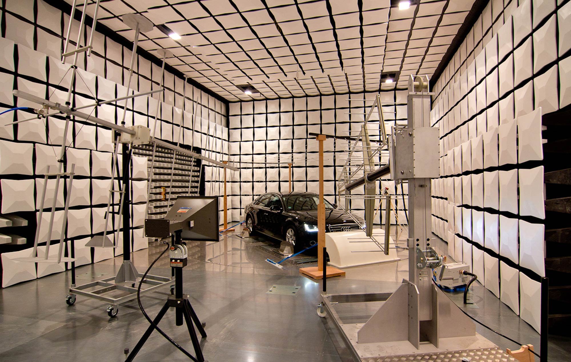
Section 20, “RF Susceptibility (Radiated and Conducted)” covers similar test methods to MIL-STD-461 CS114 and RS103. The radiated test includes both semi-anechoic and reverb methods.
Section 21, “Emission of RF Energy”, covers similar test methods to MIL-STD-461 CE102 and RE102. As in Section 20, the radiated test includes both ALSE and reverb methods.
TIP:
Use reverb testing whenever possible to save time. DO-160G Section 20 has excellent information about the mathematical and statistical techniques needed to ensure a chamber is set up correctly. The math is scarier, but there’s a significant savings in terms of testing time-in-chamber.
Sections 22 and 23 cover lightning testing (“Lightning Induced Transient Susceptibility” and “Lightning Direct Effects”). These share a lot of heritage with MIL-STD-464 as electromagnetic environmental effects tests. Section 25 covers ESD, and like most ESD specs basically follows IEC 61000-4-2.
TIP:
One of the things that separates DO-160 from other standards is the use of alphanumeric codes to describe the EUT and the applicable tests. Whenever you pin down a letter/number designation that applies to your EUT, write it down somewhere. Otherwise you’ll spend a lot of time flipping back and forth across many pages trying to find the right code again.
SpaceX Payload User’s Guides
SpaceX User’s Guides are particularly useful in summarizing EM environments for launch and ground handling.
SpaceX provides “User’s Guides” (Payload User’s Guides, or PUGs) for payloads going on Falcon 9, Falcon Heavy, or taking advantage of its Rideshare program. They’re all free to download from SpaceX. These are fairly comprehensive documents, including mission planning timelines and different environments: thermal, shock/vibe, pressure, etc., along with necessary mechanical and electrical interface specs. For our purposes, the section within “Environments” on “Electromagnetic” can be useful beyond only specific payload missions.
The purpose of this section is to let the user know what electromagnetic environments it might be exposed to, and also how it must limit its emissions in order to protect the RF and avionics systems of the launch vehicle. The limits are, on the whole, more lenient than the default limits found in MIL-STD-461, both for emissions and susceptibility, and can be very useful for tailoring EMC requirements and testing.
What I find particularly helpful is the set of limits in the image below. This is an envelope of the worst-case EM radiation environment between both the Eastern and Western launch ranges where SpaceX operates. (Presumably when Starship gets its own User’s Guide, the environment for the Texas base will be included as well.) This is incredibly helpful for planning what levels a piece of equipment should be robust enough to handle during all phases of operations leading up to launch: shipping, ground handling and checkouts, stacked and awaiting launch, as well as launch itself. This helps inform EMC radiated susceptibility test levels with a lot more granularity than the 20 V/m level set by MIL-STD-461, and is information that used to be hard to find.

AIAA-S-121: “Electromagnetic Compatibility Requirements for Space Equipment and Systems”
AIAA-S-121 adapts MIL-STDs 464 and 461 specifically for space missions, including ground handling and launch vehicles.
AIAA-S-121 is an interesting beast. It is a tailoring of the combination of both MIL-STD-464 (system level) and -461 (equipment/module level) with an eye to making them specifically applicable to space systems. It can be purchased from the AIAA. It was reaffirmed in 2023, and there’s an effort underway to make it a joint standard with the IEEE. It’s something that the EMC Society standards committee and also Technical Committee 8 (Aerospace EMC) have been involved in, so if that’s of interest to you, please get in touch (standards@emcunited.com).
AIAA-S-121 draws from MIL-STD-1541 and SMC-S-008 (both freely available), and has similarities with GSFC-STD-7000. However it is very much its own document and should be read independently. Generally speaking, Section 6 follows MIL-STD-464, Section 7 follows MIL-STD-461 Section 4, and Section 8 follows MIL-STD-461 Section 5. Section 7 starts with a helpful table that explains many of its deviations from MIL-STD-461. Like MIL-STDs 464 and 461, it has appendices with excellent additional information that reward the thorough reader.
TIP:
Just because a unit is compliant to MIL-STD-464 and -461 does not guarantee that it will be successful in meeting AIAA-S-121. At a minimum, the radiated susceptibility levels are different. MIL-STD-461 RS103 for space systems specifies a threat level of 20 V/m, where AIAA-S-121 requires levels up to 50 or 100 V/m depending on frequency range and mission phase.
TIP:
For those concerned about Multipaction in space RF systems, MIL-STD-464 requires verification by test but does not specify or even recommend or reference a specific test method. AIAA-S-121 helps us out by pointing to “ECSS-E-20-01A, Space Engineering – Multipaction and Test, European Space Agency (ESA) for the European Cooperation for Space Standardization (ECSS), 5 May 2003.”
MIL-STD-464: “Electromagnetic Environmental Effects Requirements for Systems”
MIL-STD-464 is the main aerospace/defense document that applies E3 requirements to full systems and platforms.
MIL-STD-464 is an interesting beast, less well known than its counterpart MIL-STD-461. MIL-STD-464 is currently on Rev D and can be officially downloaded for free.
This document is concerned with making sure full systems (aircraft, tanks, etc.) are able to operate safely in regards to all the potential threats from the electromagnetic environment. Testing to MIL-STD-461 is part of making sure that a given component will integrate safely with the larger platform, ensuring electromagnetic compatibility. However, the broader MIL-STD-464 standard has many additional concerns: making sure aircraft are safe when hit by lightning; making sure space RF systems don’t suffer from multipaction; controlling intermodulation products from RF systems installed on naval vessels; making sure that personnel and ordnance isn’t affected by the excess charge picked up by aircraft in flight, and much more. It includes sections on lightning, EMP, RADHAZ, TEMPEST, ESD and several others. So while it is one of the primary sources of EMC requirements on defense and aerospace projects, it encompasses a much broader universe of E3 (electromagnetic environmental effects).
TIP:
As with MIL-STD-461, anyone who takes the extra time to read the appendices will be amply rewarded with context, lessons learned, and additional technical details.
TIP:
It was frustrating to me for a long time that MIL-STD-464 requires testing as verification for Multipaction (relevant to space RF systems), but did not give any hints or pointers to a test standard. AIAA-S-121 does include such a reference, to ECSS-E-20-01A, Space Engineering – Multipaction and Test, European Space Agency (ESA) for the European Cooperation for Space Standardization (ECSS), 5 May 2003.”
TIP:
SMC-S-008 is a good tailoring of all of MIL-STD-464 for defense satellite and launch vehicle applications. This includes multipaction, as I complained about above, lightning, and other EME concerns (not just EMC, as MIL-STD-461 addresses). It is freely publicly available, unlike AIAA-S-121.
GSFC-STD-7000B: “General Environmental Verification Standard (GEVS) for GSFC Flight Programs and Projects”
GSFC-STD-7000B contains something like a version of MIL-STD-461 specifically tailored for small, metal chassis, science satellites
GSFC-STD-7000, affectionately known as GEVS, is a huge document covering a wide variety of environmental testing, including shock, vibe, thermal, etc. For our purposes we’re only concerned with Section 2.5 on EMC. Written by John McCloskey and Ken Javor, it is worth making sure to get Rev B. While both revisions have the same approach--tailoring MIL-STD-461 for the kind of missions most common at Goddard Space Flight Center--Rev B has a greatly expanded Section 2.5.3, which serves the same function as the appendices of MIL-STD-461. It is a wealth of additional information and context on each test method and how it came to be specifically tailored in this document. This is hands-down one of my favorite standards documents, and I refer to it even when I’m not working on Goddard or NASA programs. The document is freely and officially available here.
The tailoring in GEVS is based on certain assumptions that hold true for the most common GSFC programs:
Uncrewed satellites
Generally cubes, generally smaller than 2 meters on a side
They have metal chassis
They never use structure for current return
28 Vdc power bus, sourced from batteries and recharged from solar panels
The table below shows a summary of the requirements they arrived at, and a top-level comparison with MIL-STD-461.

TIP:
One thing that I appreciate is that it includes a test not found in MIL-STD-461, which is a common mode conducted emissions test. It’s found in Section 2.5.2.1.2. While MIL-STD-461 CE101 and CE102 have differential measurements taken from a LISN, this test uses a current probe to measure the common mode currents flowing on the cables--which is one of the prime indications of potential crosstalk or radiated emissions problems. It also has a method for extending the test range from 30 MHz up to 200 MHz using an absorbing clamp as described in CISPR 16-1-4. GEVS section 2.5.3.3.2.1 contains an extremely thorough and well-thought-out discussion of why absorbing clamps are appropriate at the higher frequencies, and it left me thoroughly convinced. For people in the automotive industry, the 30 - 200 MHz is particularly critical for EVs seeking to pass CISPR 12 testing, and the common mode, absorber clamp method may be a useful pre-compliance test for that purpose.
TIP:
Instead of the more commonly found 50 uH or 5 uH LISNs used in much MIL-STD-461 and automotive component testing, GEVS uses a 10,000 uF cap network. It’s worth reading the rationale in Section 2.5.3.2.2 (with related discussion in MIL-STD-461 Rev G Section A.4.3.6) to broaden your thinking about LISN/Artificial Network choice. For more on LISNs, see this post.
MIL-STD-461: “Requirements for the Control of Electromagnetic Interference Characteristics of Subsystems and Equipment”
MIL-STD-461 is one of the core EMC standards, having evolved with military applications since WWII. It is widely used in the aerospace and defense sectors.
MIL-STD-461 is a landmark document in the world of EMC standards, and there are a lot of other standards that derive from this one. The easiest place to find a copy of MIL-STD-461 (free, as most government standards are) is here, or the official site is here. The current edition is Rev G, and the working group for the standard is currently drafting Rev H.
MIL-STD-461 is more of a document that specifies test methods than a strict requirements document, and while it has suggested limits for many of the tests, in most cases those limits should be tailored. For general aerospace and defense projects MIL-STD-464 is the actual requirements document, and the tests in MIL-STD-461 are how you document compliance to the EMC requirements.
TIP:
Tailor, tailor, tailor! Beware of any project that simply tells you to “meet 461”--even accepting 461 as the overarching requirement, tailoring 461 is key for saving testing time and budget and not wasting resources designing to inappropriate or inapplicable requirements. I’ll discuss this more in articles dedicated to each test method.
TIP:
Read the appendices! More than most standards, the committee behind MIL-STD-461 documents background information for every section of the main document. This includes context, lessons learned, and why different changes have been made over time. There’s a wealth of information in there.
TIP:
MIL-STD-461 does not have a requirement to perform testing in a certified lab. While many of the labs that have the equipment needed to perform 461 testing are certified (to ISO, by ANLAB or A2LA, etc), that is not required. Testing in an uncertified lab or your own facility is allowed as long as you can meet the test equipment and test reporting requirements.